DEFINITY Enterprise Communications Server Release 7
Maintenance for R7r
555-230-126
Issue 4
June 1999
Maintenance Object Repair Procedures
9-1383SNC-BD (Switch Node Clock Circuit Pack)
9
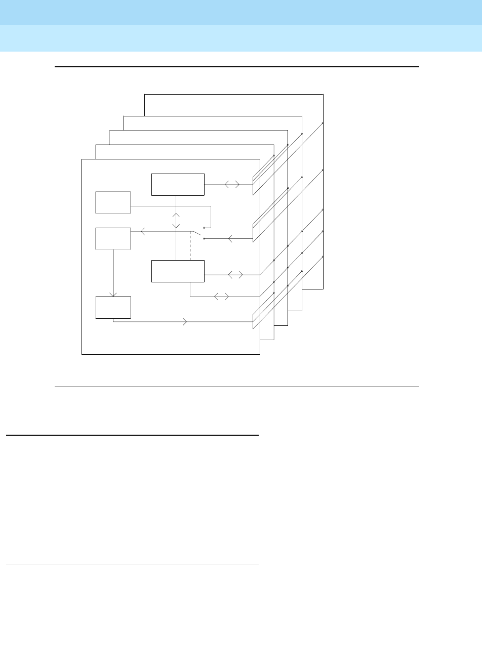
Figure 9-83. SNC Functions
SNC LEDs
SNC circuit packs have the standard red, green and yellow LEDs. The red and
green LEDs operate as usual: red means an alarm condition and green indicates
maintenance testing in progress. If the yellow LED is lit this indicates that the
SNC is the active circuit pack, supplying timing to the carrier. In a high reliability
system (duplicated SPE, simplex PNC), the standby SNC on a carrier will be
unlit. In a critical reliability system (duplicated PNC), an SNC on a standby switch
node carrier will be lit since it is providing timing for the standby carrier.
Clear Firmware-Counters Command
SNC firmware generates error reports independently of technician-demanded
tests. Therefore, the test board UUCSS clear command will not affect the error
status reported by firmware. The clear firmware-counters command will clear
all firmware-generated errors unconditionally.
The clear firmware-counters UUCSS command sends a downlink message to
the SNC circuit pack, causing it to clear out its firmware error counters and failure
Clock Duplication
9 Clock Busses
SNC-BD
SNC-BD
SNC-LINK
(aux data 1)
SNC-REF
SNC-LINK
(aux data 2)
TPN Links
Reference Signals
Serial Channel
.
Loop
Locked
Phase
Circuit
Generation
Clock
Microcontroller
.
.
.
.
Active SNC
Standby SNC
SNI 1e02
SNI 1e20
SNI 1e03
.
Microcontroller
TPN
Oscillator
Stratum 3
Control
16
SNI (TN573)
17


