DEFINITY Enterprise Communications Server Release 7
Maintenance for R7r
555-230-126
Issue 4
June 1999
Maintenance Object Repair Procedures
9-789EXP-INTF (Expansion Interface Circuit Pack)
9
■ Active EI circuit packs:
— Have their yellow LED on solid (for an inter-EPN EI in a direct
connect system) o
— Blink a pattern of 2 seconds on and 200 ms off.
■ The standby PNC EI circuit packs should have their yellow LEDs off.
Another way to determine which PNC (and therefore, which EI(s) in a port
network) is active and which is standby, use the
status port-network
and
status
PNC
commands.
See Table 9-304
for the possible EI yellow LED states.
Notes:
a. This flashing state corresponds to error codes 769 and 770 from the
Hardware Error Log and indicates a failure of Test #238. These error codes
are usually accompanied by error code 1281 (no Expansion Interface or
Switch Node Interface detected on opposite end of fiber). This condition
may be caused by the absence of the neighbor Expansion Interface or
Switch Node Interface circuit pack, a broken or missing fiber, or a missing
lightwave transceiver on either endpoint (Expansion Interface or Switch
Node Interface circuit packs).
b. This corresponds to error code 1281 from the Hardware Error Log and
indicates a failure of Test #237. This condition is usually due to the failure
of this Expansion Interface circuit pack or a failed Expansion Interface or
Switch Node Interface circuit pack counterpart.
c. This is the normal state for an Active EPN Expansion Interface circuit pack
that is also the bus master (Expansion Archangel) in the EPN.
d. This is the normal state for an Active Expansion Interface circuit pack that
is not the bus master (Expansion Archangel) for an EPN. This applies only
in the direct-connect configuration where the Expansion Interface circuit
pack in an EPN is connected via a fiber link to an Expansion Interface
circuit pack in the other EPN. This state also applies for an active
Expansion Interface circuit pack located in the PPN.
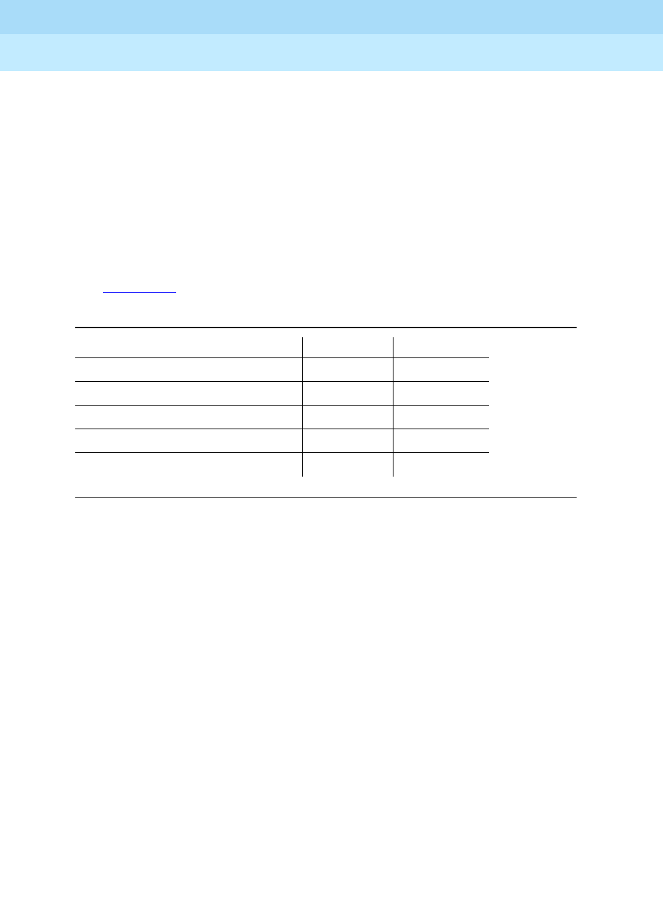
Table 9-304. Expansion Interface Circuit Pack Yellow LED Flashing States
Condition LED On LED Off
Fiber Out-of-Frame (a) 0.1 second 0.1 second
In frame-No Neighbor (b) 0.5 second 0.5 second
Expansion Interface Active (c) 2 second 0.2 second
Expansion Interface Active (d) solid on never off
Expansion Interface Standby (e) never on solid off


