


Allen-Bradley 1336-Series AC Drives
F232120
88
© Copyright, Alliance Laundry Systems LLC – DO NOT COPY or TRANSMIT
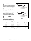
Control Terminal Blocks Description and
Control Logic
Control terminal functions are unique to each Allen-
Bradley Drive. Each drive’s control terminal is
addressed independently.
Control Terminal (TB2/TB3) Function
NOTE: Do not connect drive common terminals
(TB2 or TB3) to ground. There must be no ground
potential difference between source and drive.
Input Mode Parameter
The control terminal functions are determined in part
by the Input Mode parameter #21. Changing this
parameter affects the function of some terminals. All
machines equipped with A-B 1336 drives use Input
Mode “12”.
NOTE: If the Input Mode is changed, power must
be cycled to the drive for the change to take effect.
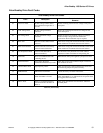
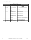
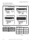
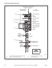
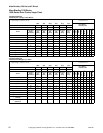
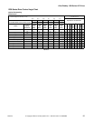
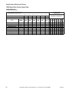
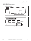
Speed Selection
Motor speeds are controlled by solid state or
mechanical switch closure inputs to SW1, SW2, and
SW3 in conjunction with STR and STF (direction)
inputs. Refer to Figure 50 and Table 50.
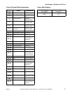
Table 50 designates the preset speed selection based
on the inputs to the control terminals. A disconnected
control terminal will seek the high control voltage
condition (approx. 5 Volts DC). To activate a control
input (i.e., SW1, SW2, etc.), the terminal is connected
to a common terminal (TB3-21, TB3-25, or TB3-29)
to lower the control voltage to a low condition (less
than 1 Volt DC).
The Input Status’ display of 1s and 0s represents the
drive’s display of parameter #55. These inputs can be
viewed in the status display with a Human Interface
Module (HIM or parameter unit). Parameter #55
displays the Input Status. When voltage is high
(inactive) for an input, the status display will read “0”
(Logic 0). When voltage is low (active) for an input,
the status display will read “1” (Logic 1).
Table 50 contains the correct display value for each
function. The sixth display digit from the left in Input
Status parameter does not correspond to a control
input function. Refer to Table 50.
NOTE: The Preset Speed logic is specific to the
type of computer the machine is equipped with (i.e.,
WE-6 or V-Computer).
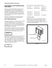
Balance Output
The AC drive Balance Output is transmitted to the
machine controller by the closure of an on-board
normally open mechanical relay shown in Figure 50.
This action occurs at distribution speed connecting
TB3-16 and TB3-17 when the drive detects an
acceptable balance condition.
Stop Input (Door Interlock /Out-of-Balance
Switch)
The Stop Input function is machine dependent. The
input is used in some machines to disable the drive in
case of an excessive out-of-balance condition; in
others, the input is used to disable the drive when the
door is open. Refer to the applicable electrical
schematic to see the correct wiring of this input. The
control inputs must be removed and reapplied to the
drive for motion after a STOP input has been
interrupted.
Jumpered Inputs
Carefully review electrical schematics when replacing
a drive. Some machine models jumper the STOP,
Motor Temp Input, and/or ENABLE inputs to the
drive (refer to Figure 50).
NOTE: Wire or metal clip jumpers may be used
and can be easily overlooked during a replacement.
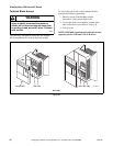
WARNING
To reduce risk of electric shock, severe
injury or death, allow machine power to
remain off for three minutes minimum prior
to working in and around AC drive. Proceed
with caution.
W662
WARNING
The controller is supplied with an internal 5V
supply. Dry contacts or open collectors are
required for discrete control inputs. If an
external voltage is applied, component
failure could occur.
W670
CAUTION
MACHINE DAMAGE AND/OR PERSONAL
INJURY. Balance output terminals TB2-16
and TB2-17 should never be jumpered. This
action will force machine beyond designed
tolerances.
W666