


Allen-Bradley 160-Series AC Drives
F232120
40
© Copyright, Alliance Laundry Systems LLC – DO NOT COPY or TRANSMIT
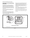
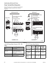
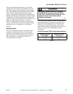
Power Terminal Block Description
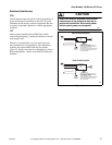
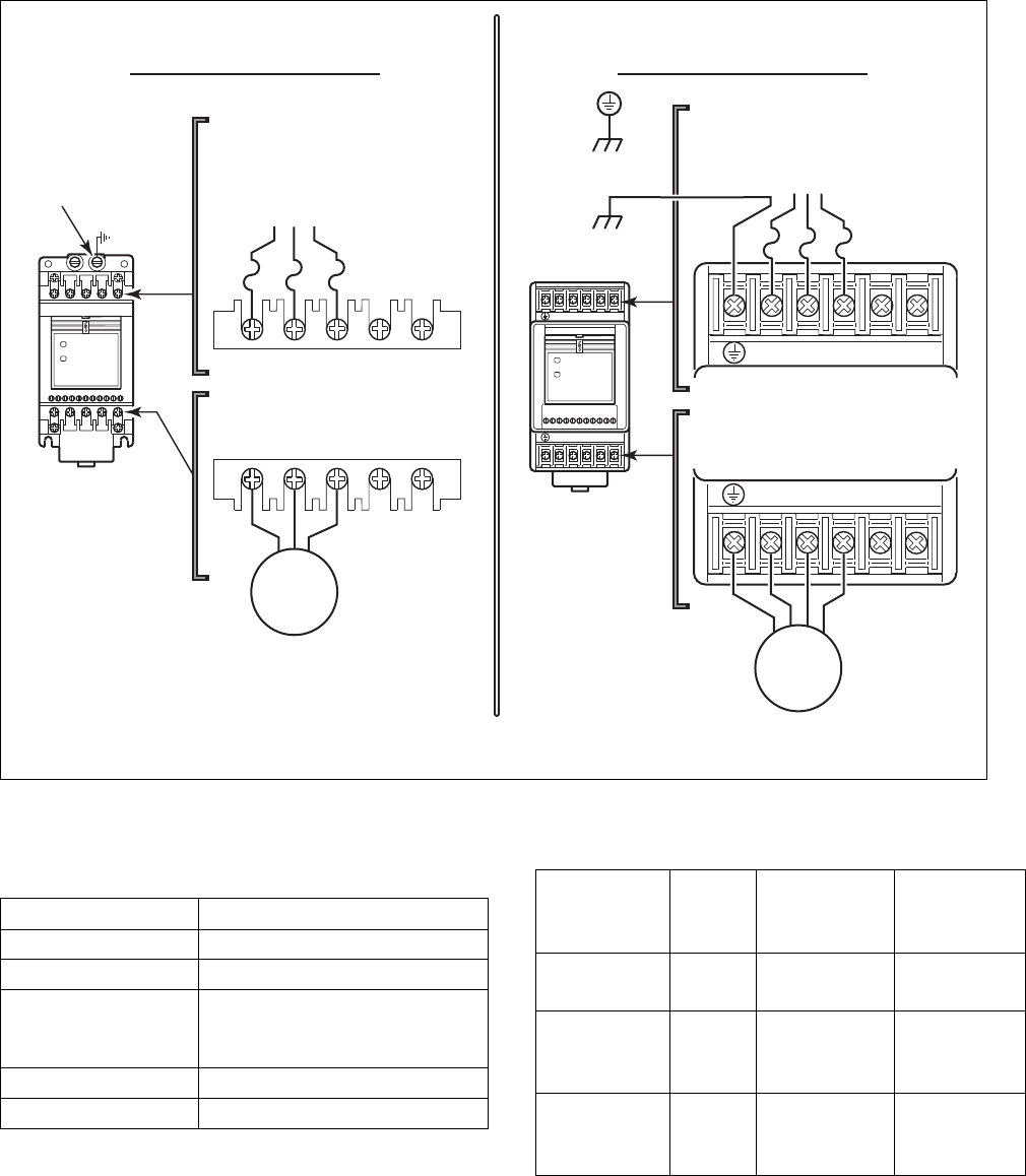
Input and output power connections are performed
through two separate terminal blocks. Refer to
Figure 23.
Figure 23
A-B 160 Power Block Terminal (TB1, TB2,
GRD)
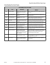
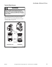
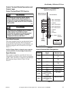
A-B 160 Torque Specifications
Table 24
L1
R
L2
S
L3
T
BR
-
BR
+
T1
U
T2
V
T3
W
-
DC
+
DC
MOTOR
Ground Tab
Protected AC Input
Terminal Block Two (TB2) -
For Motor
Terminal Block Two (TB2) -
For Motor
Terminal Block One (TB1) -
For Line Power
Protected AC Input
Terminal Block One (TB1) -
For Line Power
FAULT
READY
MOTOR
R/
L1
S/
L2
T/
L3 BR- BR+
U/
T1
V/
T2
W/
T3 DC- DC+
Chassis
Chassis
160 Series C160 Series A & B
FAULT
READY
R/L1
1 2 3 45 6 78 9 1011
S/L2T/L3BR-BR+
U/T1 V/T2W/T3DC-DC+
U165ME3A
160 SERIES A & B
160 SERIES C
U165ME3A
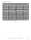
Terminals Description
GRD Earth Ground
R, S, T (L1, L2, L3) AC Input Line Terminals
BR+, BR- Dynamic Brake Resistor
Option – Refer to instructions
with option
DC+, DC- Capacitor Module Option
U, V, W (T1, T2, T3) Motor Connection
Table 23
Terminal
Screw
Size
Max/Min Wire
Size mm
2
(AWG)
Max/Min
Torque
N-m (lb-in)
TB1 & TB2
Series A & B
M4 4/0.75
(12/18)
1.81/1.35
(16/12)
4.0 kW
(7.5 HPDP)
Series C
M4 5.26 – 3.31
(10 – 12)
1.35 – 0.90
(12 – 8)
All Other
Ratings
Series C
M4 3.31 – 0.82
(12 – 18)
1.35 – 0.90
(12 – 8)