


Allen-Bradley 1305-Series AC Drives
F232120
66
© Copyright, Alliance Laundry Systems LLC – DO NOT COPY or TRANSMIT
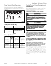
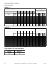
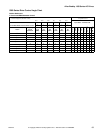
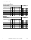
The Input Status’ display of 1s and 0s represents the
drive’s display of parameter #55. These inputs can be
viewed in the status display with a Human Interface
Module (HIM or parameter unit). Parameter #55
displays the Input Status. When voltage is high
(inactive) for an input, the status display will read “0”
(Logic 0). When voltage is low (active) for an input,
the status display will read “1” (Logic 1).
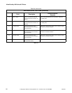
Table 44 contains the correct display value for each
function.
The first digit in the Input Status parameter does not
correspond to a control input function. Refer to
Table 44.
NOTE: The Preset Speed logic is specific to the
type of computer the machine is equipped with (i.e.,
WE-6 or V-Control).
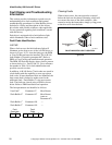
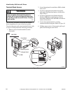
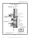
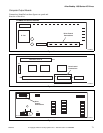
Balance Output
The Balance Output is transmitted to the machine
controller by the closure of a normally open
mechanical relay shown in Figure 40. This action
occurs at distribution speed connecting TB2-9 and
TB2-10 when the drive detects an acceptable balance
condition.
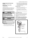
A secondary out-of-balance switch has been added to
some machine models to prevent an extreme out-of-
balance load from spinning. The switch opens the
Enable or STOP input which disables the drive. The
control inputs must be removed and reapplied to the
drive for motion to resume after a STOP or Enable
input has been interrupted.
Jumpered Inputs
Carefully review electrical schematics when replacing
a drive. Some machine models jumper the STOP and/
or ENABLE inputs to the drive (refer to Figure 40).
NOTE: Verify that inputs are jumpered. Wire or
metal clip jumpers may be used and can be easily
overlooked during a replacement.
Running Status
Some machines require an output from the drive
indicating the drive is running. TB2-19 and TB2-20
connect to the computer (V-Computer, EDC). The
drive connects the two terminals with a solid state
switch to indicate the drive is running.
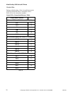
Control Terminal Block Designations
Table 39
CAUTION
MACHINE DAMAGE AND/OR PERSONAL
INJURY. Balance output terminals TB2-9
and TB2-10 should never be jumpered. This
action will force machine beyond
designated tolerances.
W664
Terminal
Number
Signal
Typical
Machine Use
1, 2, 3
External Speed Pot Specialty
Machines Only
2, 3
0 – 10V Analog Input Specialty
Machines Only
4, 3
4 – 20mA Analog Input Specialty
Machines Only
5, 3
0 – 10V Analog Output Specialty
Machines Only
6, 7
STF Forward Motion
8, 7
Stop Out-of-Balance
Switch or Jumper
9, 10
Programmable Output 1
Normally Open
Balance Relay
11, 12
Drive Enable Emergency Stop
Disable Out-of-
Balance Switch or
Jumper
13, 12
STR Reverse Motion
14, 15
Jog Unused
16, 15
SW1 Preset Speed
Input #1
17, 15
SW2 Preset Speed
Input #2
18, 15
SW3 Preset Speed
Input #3
19, 20
Programmable Output 2
Normally Open
Drive running
output
CAUTION
MACHINE DAMAGE AND/OR PERSONAL
INJURY. Never jumper inputs if not
previously configured with jumpers as
identified on the applicable electrical
schematic. Jumpering these inputs will
override safety features.
W665