


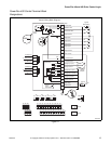

PowerFlex 40 and 400 Drive Control Logic
9
F232120
© Copyright, Alliance Laundry Systems LLC – DO NOT COPY or TRANSMIT
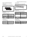
Power Terminal Block Description
PowerFlex 40
Input and Output Power Terminals (TB1)
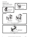
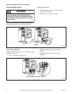
Figure 8
PowerFlex 40
Power Block Terminal (TB1)
PowerFlex 40
Power Terminal Block
PowerFlex 400
Input and Output Power Terminals (TB1)
PowerFlex 400
PowerFlex Power Block Terminal (TBI)
PowerFlex 400
Power Terminal Block
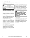
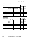
PHM741N
Terminal Description
R/L1, S/L2, T/L3 Single-phase or
3-phase Power Input
U/T1, V/T2, W/T3 3-phase Motor Output
DC-1, DC+, -DC DC Bus Connection
Ground Connection (PE)
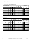
Table 3
Torque
1.7-2.2 N-m (16-19 lb-in)
Max Wire Size
5.3 mm
2
(10 AWG)
Min Wire Size
1.3 mm
2
(16 AWG)
Table 4
R/L 1
B Frame
S/L 2 T/L 3 U/T 1 V/T 2 W/T 3
DC- DC+ BR+ BR-
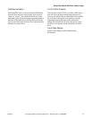
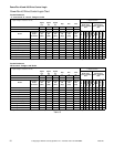
PHM742N
Figure 9
Terminal Description
R/L1, S/L2, T/L3 3-phase Power Input
U/T1, V/T2, W/T3 3-phase Motor Output
P1, P3 DC Bus inductor connection
jumper or Bus inductor must
be present for drive to power-
up.
P2, DC- DC Bus Connection
Ground Connection (PE)
Table 5
Torque
5.1N-m (45 lb-in)
Max Wire Size
33.6 mm
2
(2 AWG)
Min Wire Size
8.4 mm
2
(8 AWG)
Table 6
R/L 1
S/L 2
T/L 3
P 1
P 2
DC-
U/T 1
V/T 2
W/T 3
Frame D