


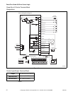
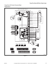

PowerFlex 40 and 400 Drive Control Logic
F232120
16
© Copyright, Alliance Laundry Systems LLC – DO NOT COPY or TRANSMIT
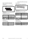
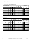
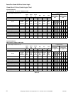
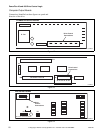
PowerFlex 40 Drive Control Logic Chart
Pocket Hardmount
“V” control and “A” control - Designs 7 and 8
H – Signal Voltage High (approximately 24V DC)
L – Signal Voltage Low (less than 1V DC)
0 = No signal received
1 = Signal received
Digital
In 3
Digital
In 2
Digital
In 1
Stop Rev Fwd
Digital Input
Status – Parameter
d014
Control Input
Status – Parameter
d013
DC Volt Meter Red Probe Terminal Location
07 06 05 01 03 02
DC Volt Meter Black Probe Terminal Location
04 04 04 04 04 04
Action
Frequency
Preset
Parameter #
Terminal
#07
(SW3)
Terminal
#06
(SW2)
Terminal
#05
(SW1)
Terminal
#01
(Stop)
Terminal
#03
(STR)
Terminal
#02
(STF)
*Digital In 4
Digital In 3
(SW3)
Digital In 2
(SW2)
Digital In 1
(SW1)
DB Trans
On
Stop
Rev (STR)
Fwd (STF)
Idle
N/A H H H L/H H H 000000/100
1/2 Wash Speed Forward
71 H H L L H L *10010101
1/2 Wash Speed Reverse
71 H H L L L H 00010110
Wash Speed Forward
72 HLHL HL*10100101
Wash Speed Reverse
72 H L H L L Ha 00100110
Distribution Speed
74 LHHL HL*11000101
Spin 1 Extract
73 H L L L H L *10110101
Spin 2 Extract
76 LLHL HL*11100101
Spin 3 Extract
75 L H L L H L *11010101
*If digital in 4 is wired to the Forward Input terminal #02, this input will be a “1” whenever the drive receives a forward command. Disregard otherwise.
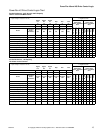
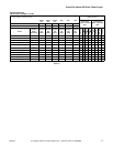
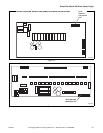
Pocket Hardmount
WE-6 control - Design 5 and Earlier
H – Signal Voltage High (approximately 24V DC)
L – Signal Voltage Low (less than 1V DC)
0 = No signal received
1 = Signal received
Digital
In 3
Digital
In 2
Digital
In 1
Stop Rev Fwd
Digital Input
Status – Parameter
d014
Control Input
Status – Parameter
d013
DC Volt Meter Red Probe Terminal Location
07 06 05 01 03 02
DC Volt Meter Black Probe Terminal Location
04 04 04 04 04 04
Action
Frequency
Preset
Parameter #
Terminal
#07
(SW3)
Terminal
#06
(SW2)
Terminal
#05
(SW1)
Terminal
#01
(Stop)
Terminal
#03
(STR)
Terminal
#02
(STF)
*Digital In 4
Digital In 3
(SW3)
Digital In 2
(SW2)
Digital In 1
(SW1)
DB Trans
On
Stop
Rev (STR)
Fwd (STF)
Idle
N/A H H H L/H H H 000000/100
1/2 Wash Speed Forward
74 L H L L H H *11000101
1/2 Wash Speed Reverse
74 L H H L L H 01000110
Wash Speed Forward
72 H L H L H H *10100101
Wash Speed Reverse
72 H L H L L H 00100110
Distribution Speed
71 H H L L H L *10010101
Medium Extract/Spray Rinse
76 L L H L H H *11100101
High 1 Extract
75 LHHLHL*11010101
High 2 Extract
73 H L L L H L *10110101
High 3 Extract
77 L L L L H L *11110101
*If digital in 4 is wired to the Forward Input terminal #02, this input will be a “1” whenever the drive receives a forward command. Disregard otherwise.
Table 10