


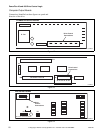
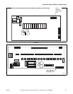
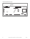
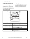
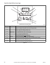
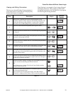

PowerFlex 40 and 400 Drive Control Logic
F232120
24
© Copyright, Alliance Laundry Systems LLC – DO NOT COPY or TRANSMIT
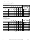
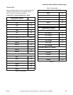
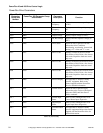
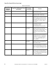
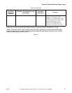
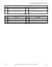
PowerFlex Drive Parameters
PowerFlex 40
Parameter
Group and
Number
PowerFlex 400 Parameter Group
and Number
Parameter
Description
Function
d001 b001 Output
Frequency
Displays instantaneous output frequency
(in Hz).
d002 b002 Command
Frequency
Displays command output frequency (in
Hz).
d003 b003 Output Current Displays output current (in Amps).
d004 b004 Output Voltage Displays output voltage (in VAC).
d005 b005 DC Bus Voltage Displays DC Bus capacitor voltage (in
VDC).
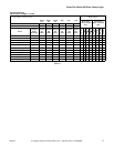
d006 b006 Drive Status Read from left to right, the four bits
indicate the drive's condition
(decelerating, accelerating, forward and
running). “0” = false and “1” = true
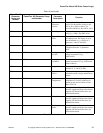
d007 d307 Fault 1 Code Memory location for the most recent
fault. Refer to Table 20 for a list of most
fault codes. Repetitive faults are stored
only once.
d008 d308 Fault 2 Code Memory location for the 2nd most recent
fault. Refer to Table 20 for a list of most
fault codes. Repetitive faults are stored
only once.
d009 d309 Fault 3 Code Memory location for the 3rd most recent
fault. Refer to Table 20 for a list of most
fault codes. Repetitive faults are stored
only once.
d010 b008 Process Display Not applicable to Alliance Laundry
Systems’ equipment. Refer to the
manual supplied with the PowerFlex
drive for detailed information.
d012 d301 Control Source Read from left to right, the digits
indicate the active source of the Speed
Reference (P038) and Start Source
(P036) command.
d013 d302 Control Input
Status
Refer to Table 8 through Table 14 for
Control Status Input diagnostics.
d014 d302 Digital Input
Status
Refer to Table 8 through Table 14 for
Digital Input Status diagnostics.
d015 d303 Communication
Status
Not applicable to Alliance Laundry
Systems' equipment. Refer to the manual
supplied with the PowerFlex drive for
detailed information.
Table 16 (continued)