


PowerFlex 40 and 400 Drive Control Logic
19
F232120
© Copyright, Alliance Laundry Systems LLC – DO NOT COPY or TRANSMIT
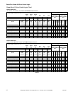
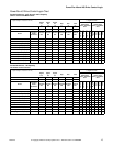
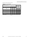
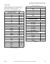
PowerFlex 40 Drive Control Logic Chart
Pocket Hardmount - IPH, IP and CP Models
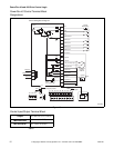
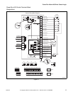
PS40 control
H – Signal Voltage High (approximately 24V DC)
L – Signal Voltage Low (less than 1V DC)
0 = No signal received
1 = Signal received
Stop Rev Fwd
Control Input Status –
Parameter d013
DC Volt Meter Red Probe Terminal Location
01 03 02
DC Volt Meter Black Probe Terminal Location
04 04 04
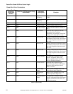
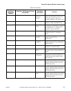
Action
Terminal
#01
Terminal
#03
Terminal
#02
DB Trans
On
Stop
Rev
Fwd
Idle
LHH0100
Wash Speed Forward
L H L 0 1 0 1
Wash Speed Reverse
L L H 0 1 1 0
Distribution Speed
L H L 0 1 0 1
Low Spin Speed
LHL0101
Medium Spin Speed
LHL0101
High Spin Speed
LHL0101
SmartSpin
LLL0111
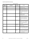
NOTE: IPH models use analog signals to control speed - refer to parameter d002 (command freq.) and d020 (analog input %)
to verify speed input signal.
Table 14