


Allen-Bradley 160-Series AC Drives
47
F232120
© Copyright, Alliance Laundry Systems LLC – DO NOT COPY or TRANSMIT
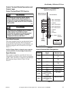
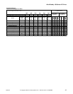
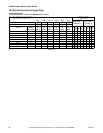
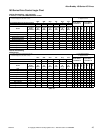
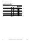
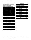
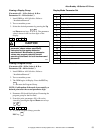
The Preset and Input Status displays of 1s and 0s
represent the drive’s display of parameters #12 and
#15. These inputs can be viewed in the status display
with a Program Key Module (Parameter Unit). Refer
to the AC drive Diagnostics/Parameter Viewing
Section. Parameter #15 displays the Preset Status and
Parameter #12 displays the Input Status. When voltage
is high (inactive) for an input, the status display will
read “0” (Logic 0). When voltage is low (active) for an
input, the status display will read “1” (Logic 1).
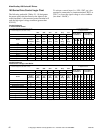
Table 31 contains the correct display value for each
function. The first digit in the Preset and Input Status
parameters do not correspond to a control input
function.
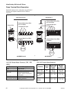
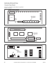
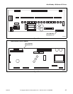
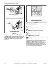
Balance Output
The AC Drive Balance Output is transmitted to the
machine controller by the closure of an on-board
normally open mechanical relay shown in Figure 24.
This action occurs at distribution speed connecting
TB3-10 and TB3-11 when the drive detects an
acceptable balance condition.
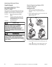
A secondary out-of-balance switch has been added to
some machine models to prevent an extreme out-of-
balance load from spinning. The switch opens the
STOP input which disables the drive. The control
inputs must be removed and reapplied to the drive for
motion to resume after a STOP input has been
interrupted.
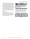
Control Terminal (TB3) Torque Specifications
Max/Min Wire Size
mm
2
(AWG)
Maximum Torque
N-m (lb-in)
2.5/0.5
(14/22)
0.8/0.4
(8/4)
Table 31
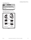
CAUTION
MACHINE DAMAGE AND/OR PERSONAL
INJURY. Balance output terminals TB3-10
and TB3-11 should never be jumpered. This
action will force the machine beyond
designed tolerances.
W669