


© Copyright, Alliance Laundry Systems LLC – DO NOT COPY or TRANSMIT
F232120
62
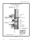
Allen-Bradley 1305-Series AC Drives
Allen-Bradley 1305-Series AC Drives
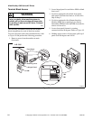
Installation/Wiring
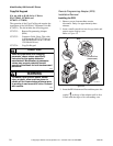
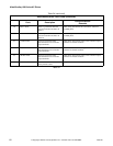
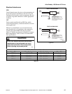
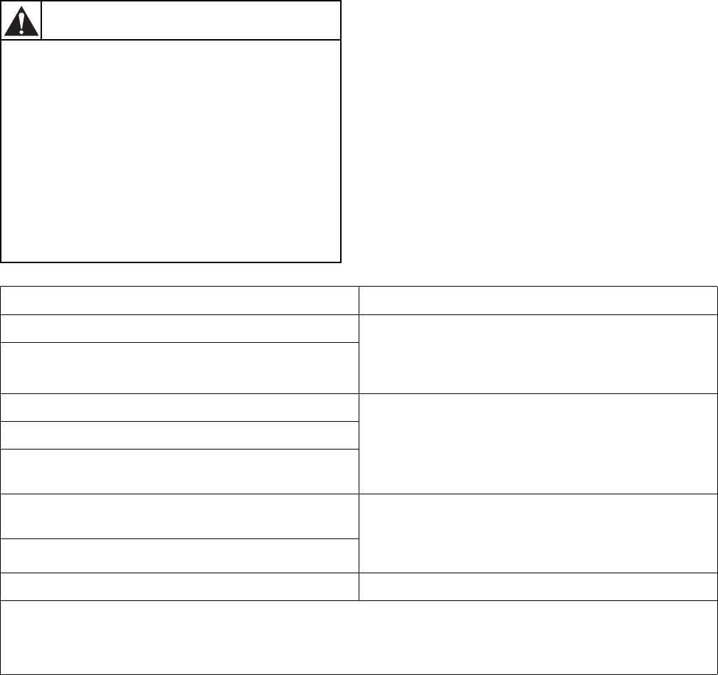
Input Power Conditioning
The drive is suitable for direct connection to input
power within the rated voltage of the drive. Listed in
Table 35
are certain input power conditions which may
cause component damage or reduction in product life.
If any of the conditions exist, as described in Table 35,
install one of the devices listed under the heading
Corrective Action on the line side of the drive.
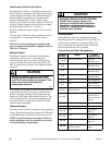
IMPORTANT: Only one device per branch circuit
is required. It should be mounted closest to the
branch and sized to handle the total current of the
branch circuit.
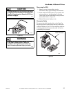
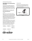
An incorrectly installed system can result in
component damage or reduction in product
life. The most common causes are:
1. Wiring AC line to drive output or control
terminals.
2. EXTERNAL voltage application to control
terminals.
3. Incorrect or inadequate AC supply.
Contact factory for assistance with
application or wiring.
W660
CAUTION
Input Power Condition Corrective Action
Low Line impedance (less than 1% line reactance)
• Install Line Reactor
• or Isolation Transformer
• or Bus Inductor – 5.5 & 11kW (7.5 & 15 HP) drives
only
Greater than 120 kVA supply transformer
Line has power factor correction capacitors
• Install Line Reactor
• or Isolation Transformer
Line has frequent power interruptions
Line has intermittent noise spikes in excess of 6000V
(lightning)
Phase to ground voltage exceeds 125% of normal line to line
voltage
• Remove MOV jumper to ground.
• or Install Isolation Transformer with grounded
secondary
if necessary
Ungrounded distribution system
240V open delta configuration (stinger leg)
(1)
• Install Line Reactor
(1)
For drives applied on an open delta with a middle phase grounded neutral system, the phase opposite the phase that is tapped in the
middle to the neutral or earth is referred to as the “stinger leg,” “high leg,” “red leg,” etc. This leg should be identified throughout the
system with red or orange tape on the wire at each connection point. The stinger leg should be connected to the center Phase B on the
reactor.
Table 35