


PowerFlex 40 and 400 Drive Control Logic
F232120
10
© Copyright, Alliance Laundry Systems LLC – DO NOT COPY or TRANSMIT
Control Terminal Blocks Description and
Control Logic
NOTE: Do not connect AC drive digital common,
analog common, or common terminals to chassis
ground.
Input Mode Parameter
The control terminal functions are determined in part
by the “Start Source” parameter #36. Changing this
parameter affects the function of some terminals.
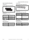
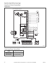
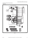
Speed Selection
Motor speeds on digitally-controlled AC drives are
controlled by solid state or mechanical switch closure
inputs to Digital In 1, Digital In 2, and Digital In 3
terminals. Similarly, motor rotation direction is
controlled by inputs to Start/Run FWD and Direction/
Run REV terminals. Refer to Figure 10.
An inactive control input terminal (H) will measure
approximately 24v DC while an active control input
terminal (L) will measure less than 1v DC. When a
control input (i.e., Digital In 1, 2, 3, 4, Fwd, Rev, or
Stop) is connected to a common terminal (terminal 4),
the voltage on the control input terminal is reduced to
near zero and the input is activated.
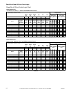
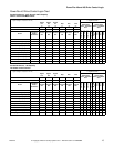
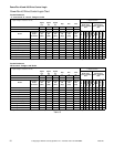
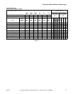
Tables 8 – 14 designate the speed and rotation
direction based on inputs to the control terminals. The
AC drive’s input status parameters display of 1s and 0s
at various machine actions can be viewed while
monitoring parameter #13 and/or #14. When the
control input terminal voltage is high (inactive) the
status display will read “0” (logic 0). When the control
input terminal voltage is low (active) the status will
read “1” (logic 1).
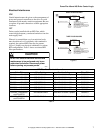
Balance Output
The AC drive balance output signal is transmitted to
the machine controller by the operation of an on-board
normally open relay or transistor. Refer to Figure 10.
The AC drive will analyze the wash load distribution
during certain drain steps and communicate the
severity of load imbalance to the machine controller.
The machine controller then determines if the load is
suitably distributed for the programmed spin speed.
The severity of load imbalance is communicated
digitally by the on-board relay or transistor using a
series of pulses or continuous open or closed state.
Stop/Enable Input
The Stop Input function is machine dependent. The
input is typically used to disable the drive either when
the frame vibration safety limit switch has been
tripped or when the loading door has been opened.
Refer to the applicable machine electrical schematic
for details on the connection of this input. When the
Stop Input signal is interrupted, the control input
signals must be removed and reapplied to restart the
motor operation.
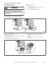
WARNING
To reduce risk of electric shock, severe
injury or death, allow machine power to
remain off for three minutes minimum prior
to working in and around AC drive. Proceed
with caution.
W662
CAUTION
Never permanently jumper the AC drive
balance output terminals or short the wires
in these terminals together. This will
override the balance detection routine and
cause the wash cycle to abort, potentially
causing machine damage or personal injury
in the process.
W671