


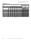
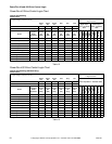
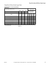
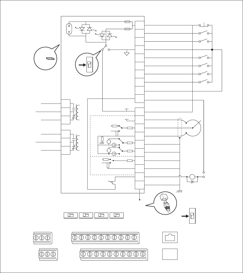
PowerFlex 40 and 400 Drive Control Logic
13
F232120
© Copyright, Alliance Laundry Systems LLC – DO NOT COPY or TRANSMIT
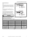
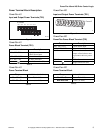
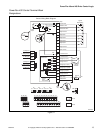
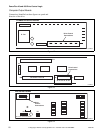
PowerFlex 400 Control Terminal Block
Designations
PHM781N
Figure 11
PHM781N
+
-
+
-
0-10V
0-10V
Isolated
18
17
16
15
14
13
12
11
19
20
10090706 080504030201
20191716 181514131211
R6
R3
Opto Output
AS485 Shield
Analog Common 2
Analog Input 2 (AI2)
Analog Output 2 (AO2)
Analog Output 1(AO1)
Analog Common 1
Analog Input 1 (AI1)
+ 10V DC Source
+ 24V DC Source
Opto Common
Digital Common
Digital Input 4
Digital Input 3
Digital Input 2
Digital Input 1
Digital Common
Direction/Run REV
Start/Run FWD
Stop /
Function Loss
1 of 7 Digital Input Circuits
SNK SRC
+10V
0-10V
0-20mA
+24V
0-20mA
30V DC
50mA
Non-inductive
A01
10V 20mA
A02
10V 20mA
AI1
10V 20mA
AI1
RS485
(DSI)
RS485
RS485
10V 20mA
#2 Relay N.O.
#2 Relay Common
#2 Relay N.C.
Pot must be
1-10k ohm
2 Watt Min.
Common
24V
Enable
Jumper
Earth Referenced
Frames D & E
ENBL
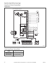
Control Wiring Block Diagram
SNK
SRC
R2R1
R6R5R4
R5
R4
R3
#1 Relay N.O.
#1 Relay Common
#1 Relay N.C.
R2
R1
08
07
06
05
04
03
02
01
09
10
Typical
SNK Wiring
SNK
SRC