


Allen-Bradley 1336-Series AC Drives
87
F232120
© Copyright, Alliance Laundry Systems LLC – DO NOT COPY or TRANSMIT
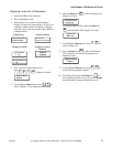
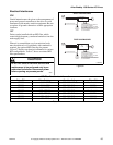
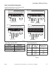
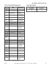
Power Terminal Block Description
Input and output connections are performed through
terminal block TB1. Refer to Figure 49.
Figure 49
Power Block Terminal (TB1) Torque Specifications
GRD GRD R
(L1)
S
(L2)
T
(L3)
DC
+
DC
-
U
(T1)
V
(T2)
W
(T3)
To
Motor
To Motor
Protected AC Input
200-240V, 0.37 Ð 3.7 kW (0.5 Ð 5 HP) Terminal Designations
380-480V, 0.37 Ð 3.7 kW (7.5 Ð 10 HP) Terminal Designations
A1-A3 Frame
U083ME3A
DC
-
COM
BRK
-
Dynamic Brake
2
DC
Input Line
GRD GRD R
(L1)
S
(L2)
T
(L3)
DC
+
U
(T1)
V
(T2)
W
(T3)
To
Motor
To Motor
Protected
AC Input
380-480V, 5.5 Ð 7.5 kW (7.5 Ð 10 HP) Terminal Designations
A
4 Frame
U084ME3
A
Dynamic Brake
PE PE R
(L1)
S
(L2)
T
(L3)
DC
+
DC
-
U
(T1)
V
(T2)
W
(T3)
To
Motor
To Motor
Protected
AC Input
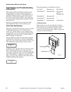
200-240V, 5.5 kW (7.5 HP) Terminal Designations
380-480V/500-600V, 5.5 Ð 11 kW (7.5 Ð 15 HP) Terminal Designations
B1
Frame
U085ME3A
B2 Frame
Dynamic Brake
To
Motor
To Motor
Protected
AC Input
PE PE R
(L1)
S
(L2)
T
(L3)
DC
+
DC
-
U
(T1)
V
(T2)
W
(T3)
200-240V, 7.5 Ð 11 kW (10 Ð 15 HP) Terminal Designations
380-480V, 15 Ð 22 kW (20 Ð 30 HP) Terminal Designations
U086ME3A
Terminal Description
PE Potential Earth Ground
R (L1), S (L2), T (L3) AC Line Input Terminals
+DC, -DC DC Bus Terminals
U (T1), V (T2), W (T3) Motor Connection
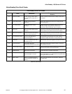
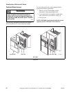
Table 48
Drive
Frame
Size
Max./Min. Wire
Size*
mm
2
(AWG)
Maximum Torque
N-m (lb.-in.)
A1-A4 5.3/0.8
(10/18)
1.81
(16)
B1 8.4/0.8
(8/18)
1.81
(16)
B2 13.3/0.5
(6/20)
1.70
(15)
*
Wire sizes given are maximum/minimum sizes that TB1 will accept –
these are not recommendations.
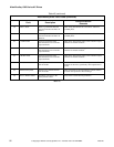
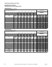
Table 49