


Allen-Bradley 1305-Series AC Drives
65
F232120
© Copyright, Alliance Laundry Systems LLC – DO NOT COPY or TRANSMIT
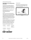
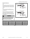
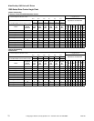
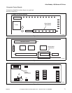
Power Terminal Block Description
Input and output power connections are performed
through a ten-position terminal block, TB1. Refer to
Figure 39.
Figure 39
Power Block Terminal (TB1)
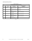
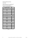
Torque Specifications
Table 38
Control Terminal Blocks Description and
Control Logic
Control terminal functions are unique to each Allen-
Bradley Drive. Each drive’s control terminal is
addressed independently.
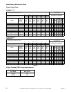
Control Terminal Block (TB2) Function
Input Mode Parameter
The control terminal functions are determined in part
by the Input Mode parameter #21. Changing this
parameter affects the function of some terminals. All
machines equipped with 1305 drives use Input Mode
“UNIMAC”.
NOTE: If the Input Mode is changed, power must
be cycled to the drive for the change to take effect.
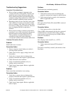
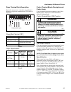
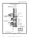
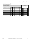
Speed Selection
Motor speeds are controlled by solid state or
mechanical switch closure inputs to SW1, SW2 and
SW3 in conjunction with STR and STF (direction)
inputs. Refer to Figure 40 and Table 39.
Table 44 designates the preset speed selection based
on the inputs to the control terminals. A disconnected
control terminal will seek the high control voltage
condition (approx. 5 Volts DC). To activate a control
input (i.e., SW1, SW2, etc.), the terminal is connected
to a common terminal (TB2-7, TB2-12, or TB2-15) to
lower the control voltage to a low condition (less than 1
Vol t DC ).
U082ME3A
Terminals Description
GRD Earth Ground
R, S, T (L1, L2, L3) AC Input Line Terminals
+DC, BRK (or -DC) Dynamic Brake Option – Refer
to instructions with option
U, V, W (T1, T2, T3) Motor Connection
Table 37
Terminal
Screw
Size
Max/Min Wire
Size mm
2
(AWG)
Max/Min
Torque
N-m (lb-in)
TB1 (0.37 to
0.75 kW
1/2 to 1 HP)
M4 3.5/0.75
(12/18)
0.90
(8)
TB1 (All
except above)
M4 4/0.75
(10/18)
1.81
(16)
TB2 (All) M3.5 1.5/0.20
(14/24)
0.90
(8)
GRD GRD L1
R
L2
S
L3
T
+DC BRK
(-DC)
T1
U
T2
V
T3
W
To
Motor
To Motor
Protected AC Input
1
U082ME3A
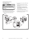
WARNING
To reduce risk of electric shock, severe
injury or death, allow machine power to
remain off for three minutes minimum prior
to working in and around AC drive. Proceed
with caution.
W662
CAUTION
The controller is supplied with an internal 5V
supply. Dry contacts or open collectors are
required for discrete control inputs. If an
external voltage is applied, component
failure could occur.
W670