


- 66 -
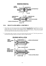
12.2 ASSEMBLY GUIDELINES
Assembly is the reverse of disassembly. The following
points are worth noting.
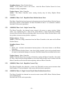
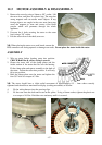
Drain Hose Outlet Elbow. Refit to the base. NB: Ensure
the lugs on the elbow are located underneath the pump
bracket. Clamp into position.
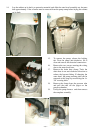
Pump. Turn the pump clockwise when refitting it into the
bayonet fixture. Check that the locking tab has clicked
into place.
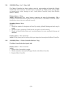
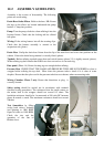
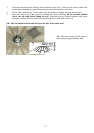
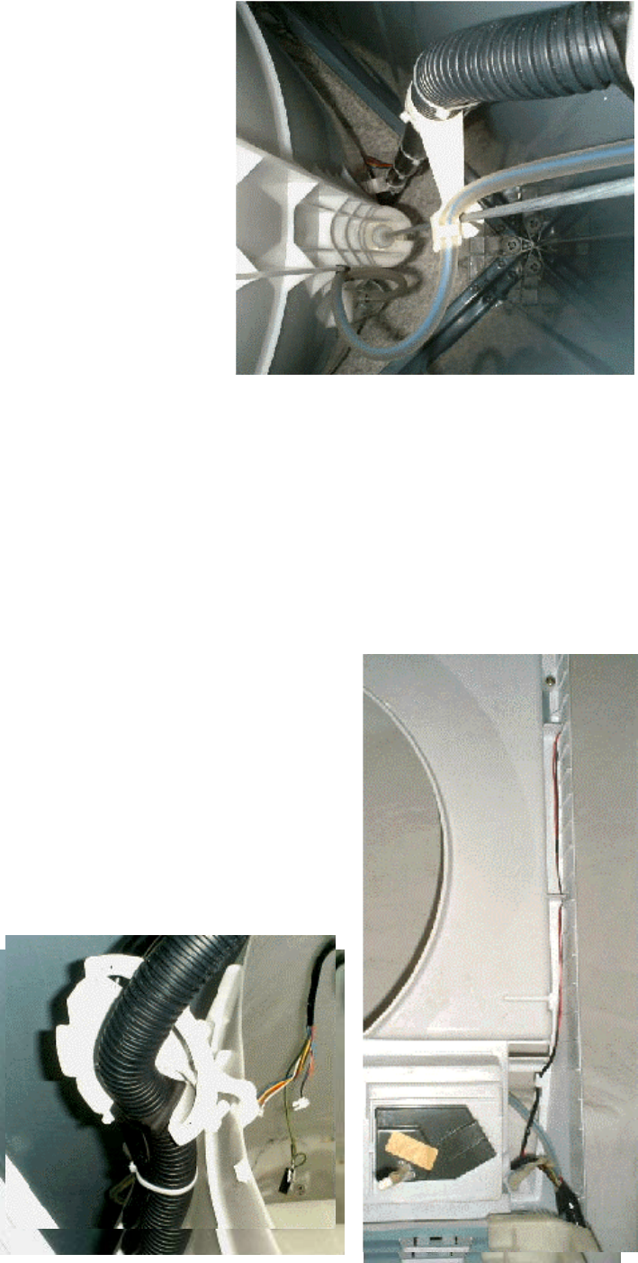
Wiring. Fit the wiring harness into all the securing clips.
Check that the harness assembly is secured to the
suspension rod, (photo).
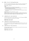
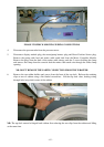
Drain Hose. Unclip the drain hose fixture from the lip of the outer bowl and screw into position on the
cabinet. Ensure the drain hose grommet is correctly fitted, (photo).
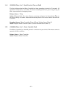
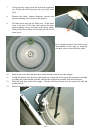
Topdeck. Before refitting topdeck ensure that reed switch harness (phase 2-5) is tightly secured, (photo).
When refitting top deck ensure that OOB lever does not catch or sit on neck ring.
Base panel. (Phase 1-4) Ensure locating tags are straight before refitting.
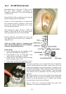
Pressure Hose. CHECK THAT THE LOOM AND PRESSURE TUBE ARE NOT KINKED or close to
wrapper before refitting the top deck. Blow down the pressure tube to check if it is clear of water
droplets. Ensure that the nylon cord in the pressure tube does not obstruct when reconnecting tube.
Mixing Chamber. Phase 5 only. Ensure that thermistor or plug is
correctly located.
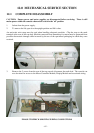
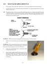
Safety testing should be carried out in accordance with standard
electrical testing procedures. The resistance from the earth contact on
the mains lead to the wrapper should not exceed 0.5 ohms. The
insulation resistance should also be measured at 500 volts DC between
phase & neutral to earth. The maximum resistance should not exceed
1Mohm.
Test Smartdrive by filling
(using both valves), draining
and spinning to 1000 RPM.
Open lid when at 1000 RPM.
Check the size and the
operation of the Out of
Balance lever.