


- 2 -
1.2 SMARTDRIVE SERVICING – Quick Reference Guide!
• Smartdrive is not isolated. Even low voltage (5v and 15v) are live!
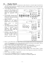
• During normal operation only one LED should be flashing. This is the leftmost wash progress LED when Smartdrive is Paused.
• The product has a diagnostic mode which allows the fault information to be displayed.
• Diagnostic mode level 3, indicates last fault. If there are no wash progress LED’s ON it would be most unlikely that the Motor Controllers has failed
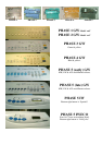
• Motor Controllers and displays of different phases are different colours. Both motor controller and display must be of the same colour to be compatible.
• Phase 1 to 4 motor controllers used water to cool the electronics. The water temperature is regulated by a thermistor within the motor controller.
• Phase 5 motor controllers use the pump to generate the low voltage power supply. If the pump is disconnected Smartdrive will appear ‘dead’.
• Phase 1 (spare), 4 & 5. When replacing Motor Controllers the size must be set, otherwise fault code 9 will occur when the product is started.
• When reconnecting the internal pressure hose ensure the product is empty of water.
• Water inlet flow problems are normally indicated by HOT &/or COLD LED’s flashing, this could mean the taps are off or the filters blocked.
• Inlet hose filters should be fitted with the dome pointing into the flow of the water on the tap end of the inlet hose.
• If the drain hose is pushed too far down into the standpipe Smartdrive could siphon during rinse.
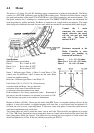
• The motor has a direct drive and has no gears. There have been 3 different stators and 2 different rotors since introducing Smartdrive.
• The inner bowl floats when the product is full of water.
• The inner bowl has balance rings which have sealed compartments full of water. These self balance the bowl during spinning.
• The pump has a thermal cut out which can take up to 15 minutes to reset. This can occur during a pump block, fault code 37.
• When servicing the pump consider fitting a pump hood kit to Phase 2-5. See WM013 in Appendix B.
• When servicing a 5kg Smartdrive pump consider fitting or a pump shield p.n. 426292. Phase 1-4. See WM81 in Appendix B.
• When servicing Phase 2-3 Smartdrive consider fitting a condensation kit to the console area. See WM80 In Appendix B.
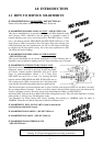
• Option Adjustment Mode. Press START/PAUSE and hold POWER.
• Diagnostic Mode. Press WASH TEMP DOWN and hold POWER.
• Size Setting Mode. Press WASH TEMP UP and hold POWER.
• Warranty does not cover problems caused by the user, for example ‘user warnings’. Pump blocks are not covered by warranty.
• Between 1995 and 2000 50% of Motor Controllers and Display Modules returned to Fisher & Paykel were not faulty.
Service information is available on the internet at the following web address www.fisherpaykel.com/Service Get appropriate usernames and passwords from your ASC’s.
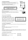
Smarttool is used to diagnose fault information and may be downloaded from this web address. This is available as a PC application or on a palmtop. The data is optically
transferred from Smartdrive, ActiveSmart(Fridge), and DishDrawer(dishwasher) using a light pen from a front panel LED.
Safety testing should be carried out in accordance with standard electrical testing procedures. The resistance from the earth contact
on the mains lead to the wrapper should not exceed 0.5 ohms. The insulation resistance should also be measured at 500 volts DC
between phase & neutral to earth. The maximum resistance should not exceed 1Mohm.