


- 9 -
4.2 Motor
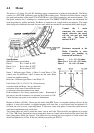
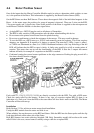
The motor is a 3 phase, 42 pole, DC brushless motor, commutation is achieved electronically. The Motor
consists of a STATOR (stationary part) and ROTOR (rotating part). The Rotor Position Sensor controls
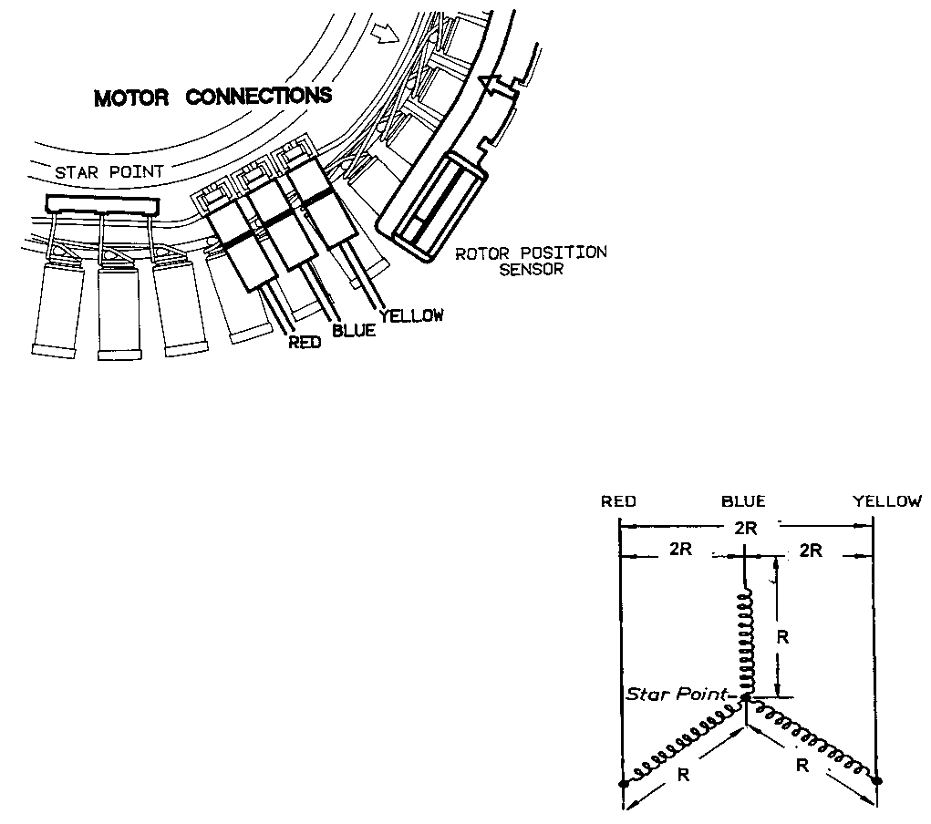
the speed and position of the motor. The STATOR has a 'star point' connection, and motor terminals. The
Star point connects the 3 windings to a common point. The DIRECT DRIVE motor has eliminated the
need for gearboxes, pulleys and belts. The Rotor is connected via a single shaft to the agitator. The single
shaft design also eliminates the need for extra seals which are needed in conventional multi shaft designs.
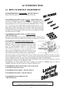
Connect the 3 stator
connectors the correct way
round, otherwise the motor
will not run and give fault
code 136. The stator is
marked “R B Y”.
Resistance measured at the
Motor Controller is twice
resistance per winding eg
between red and blue is:
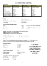
Specifications
Stator Resistance per winding
Phase 1 R=1.3 ohms @ 20
o
C
Phase 2 to 4 R=6.1 ohms @ 20
o
C
Phase 5 R=16 ohms @ 20
o
C
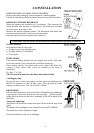
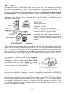
Stator. 3 different types. Phase 1, Phase 2-4 and Phase 5. The
contact sizes for the Phase 1 and 2-4 stators are the same. Phase
5 stator has smaller contacts.
Rotor has 2 different types Phase 1 and Phase 2-5.
Fault Codes 130,131,132,133,134,136 are directly
associated with the Motor. Always check the
resistance of the stator. Ensure that the rotor
is stationary when measurements are made.
If the resistance is low always replace the stator. Remember if
the stator is hot the resistances can increase by as much as 30%.
Check the brass star point is not cracked or intermittent.
Phase 1 1.3 + 1.3 = 2.6 ohms
Phase 2 to 4 6.1 + 6.1 = 12.2 ohms
Phase 5 16 + 16 = 32 ohms
Replace if broken (425104). Rotor may be tested with RPS Tester. A complete rotation will test all the
magnets. A rotor with cracked or chipped magnets will work fine. A rotor should only be replaced if it
has been run over by a bus, (especially phase 1). However, some early phase 5 rotors may cause noise on
wash and a replacement may rectify this.
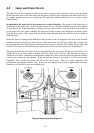
Two clamp plates are used to secure the stator, one on each side. The four bolts are tightened to a torque
of 5 Nm. NB: Early Smartdrives had a clamp plate that was riveted, these should not be mixed with the
later clamp plates which are ‘lanced’. The plastic nut for securing the rotor requires a 16mm socket and
should be tightened to 16 Nm. If the nut is broken use puller p/n 502034.