


- 11 -
4.4 Display Module
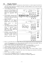
• The Display Module contains a microprocessor whose function is to take the inputs from the front
panel and send the appropriate command to the Motor Controller Module. It also controls the output
to the display LEDs and beeper.
• Test the Display LEDs. Power on
at the wall. This illuminates all
LEDs for 2 seconds. Check the
operation of all the switches and
check the appropriate LED
lights.
• If not all LEDs illuminate check
that the LEDs are not bent. Open
up housing, (with power off) and
reposition the LED.
• Replace if there is any sign of
corrosion on the Display
Module. This is one of the most
likely causes in older
Smartdrives.
• The display has up to 4 hidden
modes where the function of the
buttons is different. Option
adjustment mode, Diagnostic
mode, Size Setting mode and
Demonstration mode.
• On Phase 1 and early Phase 2
the Display Module was fitted
with the lid switch. Check it
activates correctly onto the
plastic ‘button’ in the console.
• Phase 1-3 were fitted with a size switch. This was a two pronged switch which was activated by the
console. This determined the size of the product and is located at the bottom in the middle. The size
must be set in EEPROM by accessing Option Adjust mode.
• Phase 4-5. When replacing these displays & Phase 1(spare). Size Setting Mode see section 9.0.
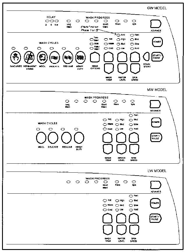
• 3 different display modules, LW, MW and GW. The AW is fitted with an LW display.
• Phase 3-5 GW has ‘Auto Water Level’. Phase 2-5 GW has ‘Delay Start’.
• Colour of the display identifies the phase. Blue (or white) is Phase 1 and 2. Green is Phase 3. Yellow
is Phase 4 and grey is Phase 5. The phase and colour of the display must match that of the Motor
Controller.
• Phase 1 (spare). See WM011 in Appendix B.
• Pressure sensor and EEPROM on Phase 1 is in display, (not phase 1 spare).
• Condensation kit may be fitted to phase 2-3 Smartdrives see WM80 in Appendix B.