


- 13 -
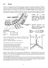
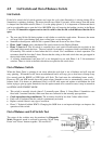
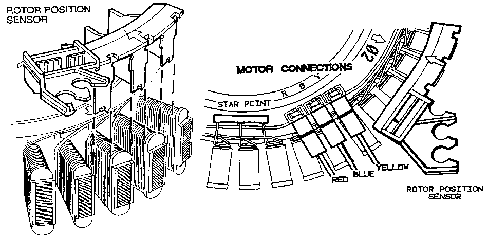
4.6 Rotor Position Sensor
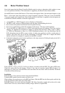
One of the inputs that the Motor Controller Module needs in order to determine which switches to turn
on, is the position of the Rotor. This information is supplied by the Rotor Position Sensor (RPS).
On the RPS there are three Hall Sensors. These detect the magnetic field of the individual magnets in the
Rotor. As the motor turns, the position of a group of magnets is detected. There are 5 wires on the RPS,
2 for power supply and 3 signal wires. Data on the position of the Rotor is supplied to the microprocessor
in the Motor Controller Module via the three signal wires.
• A single RPS p.n. 426221P may be used on all phases of Smartdrive.
• The RPS is static sensitive. ESD precautions must be taken when handling this device.
• Do not remove the printed circuit board from the plastic housing.
• Do not use a multi-meter to check the resistance of the sensors. This may result in damage.
• To test the RPS use a RPS tester p.n. 502105 and manually rotate the agitator. This tester requires
adapters, see Appendix D. It requires a 9v battery to operate. The tester has 3 LEDs. A pass is when 1
or 2 LEDs are illuminated at a time. 0 or 3 LEDs illuminated indicates a fail. Any flickering of the fail
LED will indicate that the RPS or rotor is faulty. A faulty rotor would give a fail at certain points of
rotation. This tester does not test all the functionality of the RPS. It tests the 3 outputs but cannot
indicate all faults, for example if a capacitor on the RPS is cracked.
• Conformal coating has caused contact problems on the edge connector. Pushing the plug on and off a
few times should clean the contacts.
Fault codes 53, 130,131,132,133,134,136 are directly associated with the RPS. Test with a RPS tester.
Check the strain relief for the harness. If there is any sign of corrosion replace RPS. If there is an
indication of a ‘flash over’ from the RPS to the stator there will be a black mark on the RPS. The Motor
Controller will have blown up.
Installation
Refer Section 12.3 for advice on motor removal and installation.
Unclip the RPS module from the stator and slide it out.
When refitting, line up the arrows on the RPS and Stator. Slide the RPS into the Stator poles until the clip
locks into the notch on the other side of the Stator.
Refit RPS harness into strain relieving labyrinth. NB. Early Smartdrive models did not have this strain
relief. If this is the case, secure harness carefully using a cable tie or replace RPS.