


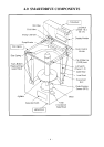

- 14 -
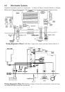
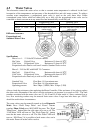
4.7 Pump
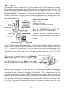
The drain pump motor is coupled directly to the base of the outer bowl. This eliminates bowl to pump
hoses and the accompanying seals, clips etc. The pump housing is an integral part of the outer bowl. The
pump is accessible by removing the inspection hatch on the front of Smartdrive, (Phase 1 to 4 only). It is
also accessible from the top by removing the agitator and inner bowl. Phase 5 uses the pump as part of
the power supply. If it is not connected, (or thermally tripped) Smartdrive will not power up. A fan is
mounted on the underside of the pump. This is necessary to keep the pump cool. The impeller, on the top
of the pump, pumps the water. Phase 5 pumps the water with a 10 second on, 1 second off timing, this
helps clear the pump of lint.
Pump Motor Specifications
230V AC 50Hz
Thermal cut-out fitted.
Flow Rate 24 L a minute @ 1m Head
Pump motor resistance
Phase 1 & 2 (SELNI) 33 ±3 ohms@ 20
o
C
Phase 1 & 2 (COMPRECCI) 26 ±3 ohms @ 20
o
C
Phase 3 to 5 (SELNI) 33 ±3 ohms @ 20
o
C
Pump block, fault code 37 is the most common, see
section 12.4 for more information. Always clear the
pump from inside the inner bowl when this fault is
reported.
Older pumps may leak along the shaft. If there is any sign of leakage the pump should be replaced.
Always check the resistance of the pump windings. If the resistance is low always replace the pump. If the
pump is hot the resistances can increase by as much as 30% before the pumps thermal cut out trips at
110
o
C. This can take 15 minutes to reset. The cut-out should only trip if there is a blocked pump. Ensure
there is a plastic fan on the underside of the pump. Burnt out pumps can be a result of a leak in the pump
seal to the outer bowl. Check for signs of leaks in the pump area. Other fault codes are 12, 13, 14, 44 and
62.
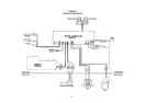
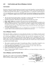
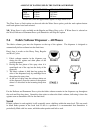
The pump may be manually turned on from Diagnostic
Mode. Diagnostic mode is accessed by pressing ‘Wash
Temp Down’ and ‘Power’ buttons together. Phase 3 Only
press ADVANCE key once. The ‘Regular’ cycle button
turns the drain pump on or off. The ‘Regular’ LED will light
when the pump is on. Use to drain the bowl.
When removing the pump up to a litre of water may leak from the pump cavity. When replacing pump
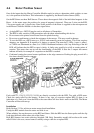
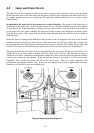
lubricate the top section of seal diaphragm. If servicing a pump block, a Pump Hood kit, (see WM013 in
Appendix B), should be fitted to all Smartdrives since late phase 2. This is an enhancement and will
reduce further pump blocks, it includes a VORTEX impleller, see above diagram. The screw securing the
pump hood to the inside of the outer bowl must be secured tightly. A pump shield (p.n .426292) should be
fitted to all 5kg Smartdrives that are not fitted with one, (typically phase 1 to 3). A Comprecci pump is
now replaced by a Selni pump. If replacing a Comprecci pump with a Selni pump an insulating divider
p.n. 425890 is required to be fitted between the terminals of the pump. The pump bracket may also be
different. The pump must be earthed.