57
Automatic Temperature Control Test
This test checks the water inlet solenoids, the temperature sensor and the control board.
• Check that the hot and cold water fill valves are working.
NOTE: This test MUST be done with the Automatic Temperature Control (ATC) selected.
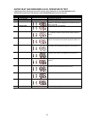
If the fill valves are working properly:
→→
→→
→ Press NORMAL or HEAVY DUTY cycle.
→→
→→
→ Press the WATER TEMP selector to set the wash water temperature to WARM.
→→
→→
→ Press START
→→
→→
→ After water has been introduced into the tub, press STOP/CANCEL once.
→→
→→
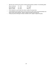
→ Measure the water temperature. At the WARM setting, the ranges should be 90-110°F.
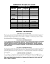
Main to FHOT
AUX to FHOT
MAIN to AUX
FTC to FHOT
MAIN to Ground
AUX to Ground
2 - 4
2 - 4
5 - 7
less than .5 (short)
infinite
infinite
P6 - 2 (RD)
P6 - 1 (YL)
P6 - 2 (RD)
P6 - 5 (WH/RD)
P6 - 2 (RD)
P6 - 1 (YL)
WINDING
CONTACTS
RESISTANCE (
ΩΩ
ΩΩ
Ω)
P6 - 4 (WH/BK)
P6 - 4 (WH/BK)
P6 - 1 (YL)
P6 - 4 (WH/BK)
Ground screw in top
Ground screw in top
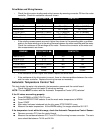
Drive Motor and Wiring Harness
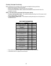
• Check the drive motor windings and wiring harness by removing connector P6 from the motor
controller. Check for resistance values as shown:
Main to FHOT
AUX to FHOT
MAIN to AUX
FTC to FHOT
MAIN to Ground
AUX to Ground
2 - 4
2 - 4
5 - 7
less than .5 (short)
infinite
infinite
RD
YL
RD
WH
RD
YL
WINDING
CONTACTS
RESISTANCE (
ΩΩ
ΩΩ
Ω)
BK
BK
YL
BK
GN/BK
GN/BK
• If the winding measurements are much higher than shown in the preceding table, a problem
exists in the motor winding or in the wiring harness between the motor controller and the motor.
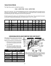
Check the resistance of the windings at the motor. Remove the connector at the motor and
take measurements as shown:
• If the resistance is much higher than shown, replace the drive motor.
• If the resistance at the drive motor is correct, there is a harness problem between the motor
and the motor controller. Replace the wiring harness as necessary.
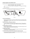
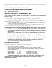
If the temperature is not within this range, check the Automatic Temperature Control Sensor:
→→
→→
→ Remove connector P13 from the control board.
→→
→→
→ Measure the resistance between P13-7 and P13-8 at the wiring harness connector. The resis
tance should be between 74 KΩ and 24 KΩ.


