


54
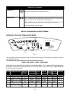
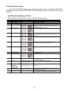
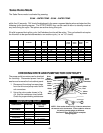
RESISTANCE CHART
COMPONENT
WINDING RESISTANCE
VALUE
Drive Motor
Pump Motor
RD to BK
YL to WH
RD to YL
RD to WH
YL to WH
RD to YL
2 - 4 ohms
2 - 4 ohms
5 - 7 ohms
10 - 12 ohms
10 - 12 ohms
20 - 25 ohms
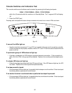
CHECKING DRIVE AND PUMP MOTOR CONTINUITY
White
Red
Yellow
Green
Green/
Black
Yellow
White
Red
Black
The pump and drive motors can be checked
for continuity. Disconnect power from the
washer and remove the front cabinet panel.
1. Disconnect the wiring harness plugs
from the drive and pump motor termi-
nal connectors.
2. Using the color codes shown in Fig.
4-4, and the resistance chart below.
Check for proper winding resistances.
Fig. 4-4
NOTE: Color codes shown in Fig. 4-4 are for wires from
the motors to the connectors. Color codes for wires to
the wiring harness plugs are different.
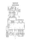
See Section Five: TECH TIPS for complete
Wiring Diagram.
Drive
Motor
Connector
Pump
Motor
Connector
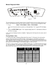
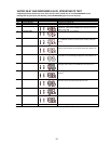
Sales Demo Mode
The Sales Demo mode is activated by pressing:
SOAK - WATER TEMP - SOAK - WATER TEMP
within five (5) seconds. “Sd” should be displayed in the seven-segment display when activated and the
following cycle should progress. The STOP/CANCEL key can be used to return to standby mode at
any time during the cycle. No options are active during this cycle.
If the lid is opened during this cycle, the Peekaboo function will be active. This cycle should not require
the lid switch to be opened afterwards to run another cycle, (i.e. no “LS” check).
PHASE STEP DESCRIPTION OF
SEQUENCE
NOTES WATER
TEMP
DISPENSER COMMENT PUMP
MOTOR
ACTION
DRI V E
MOTOR
ACTION
DRI V E
MOTOR
SPEED
DURA TI ON
(SEC)
DIAGNOSTIC 1 NUTATE 150 OFF OFF OFF NUTATE 150 8
2 SPIN 60 OFF OFF OFF SPIN 60 15
3 NUTATE 150 OFF OFF OFF NUTATE 150 5
4 NUTATE 225 OFF OFF OFF NUTATE 225 5
5 NUTATE 250 OFF OFF OFF NUTATE 250 5
6 NUTATE 275 OFF OFF OFF NUTATE 275 5
7 NUTATE 300 OFF OFF OFF NUTATE 300 5
8 SPIN 800 OFF OFF OFF SPIN 800 60
RETURN TO STANDBY OFF OFF OFF OFF 1:48