


15
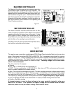
PRESSURE SWITCHES
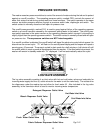
The washer uses two pressure switches to control the amount of water entering the tub and to protect
against an overfill condition. The operating pressure switch, marked OPR, controls the amount of
water that enters the tub during normal wash and rinse functions. This switch operates in the same
manner as similar pressure switches through a pressure switch tube, diaphragm and switch. The
switch contact is normally closed and will open on pressure rise.
The overfill pressure switch, marked FLD, is used to guard against failure of the operating pressure
switch or an overfill condition caused by the consumer adding water to the basket. The overfill pres-
sure switch operates in the same manner as the operating pressure switch, except it’s trip setting is
slightly higher than the operating pressure switch. The switch contact is normally closed and will open
on pressure rise. These pressure switches are NOT interchangeable.
If an overfill condition is detected, the overfill switch will signal the electronic control which causes it to
discontinue the current cycle. “FL” will flash on the control panel display and the beeper will repeat a
warning every 10 seconds. The pump is cycled in drain mode for a half minute on, half minute off until
the overfill switch is reset or power is disconnected from the washer. If the flood switch does reset, the
washer will remain in standby mode with “FL” displayed. It will not automatically restart the cycle.
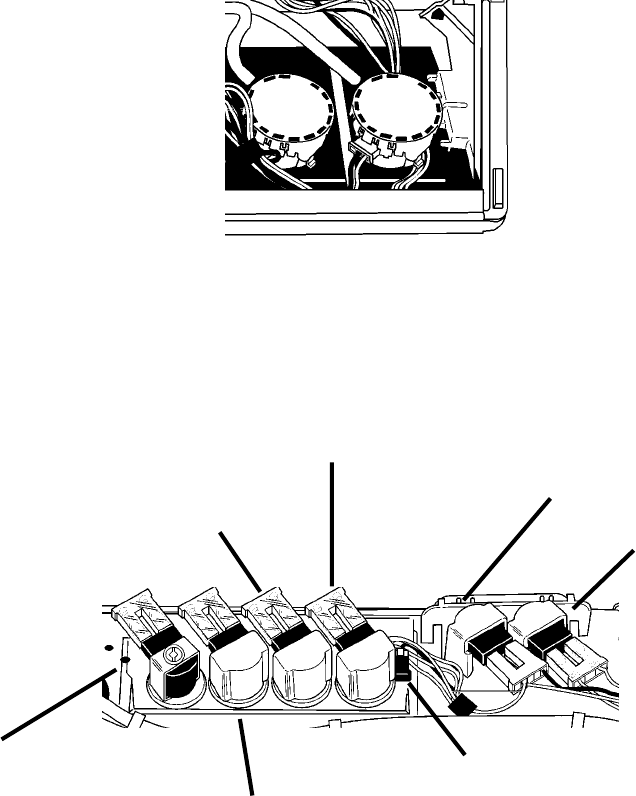
OPR
FLD
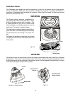
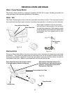
LOG VALVE ASSEMBLY
The log valve assembly consists of an inlet valve with hot and cold water valves and solenoids for
incoming water supply and four (4) outlet valves for the water to exit the valve body. The outlets drive
the dispensers under the washer top and allow for fresh water fill. Also included in the log valve
assembly, is the thermistor which is used to monitor incoming water temperature.
Bleach Dispenser Outlet Valve
Fabric Softener Dispenser Outlet Valve
Detergent Dispenser Outlet Valve
Hot Water Inlet Valve
Cold Water Inlet Valve
Thermistor
Fresh Water Outlet Valve
Fig. 2-11
Fig. 2-12