


34
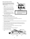
Plastic
Hoses
Harness Connectors
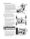
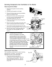
NOTE: Although the pressure switches look identi-
cal, they are not. When replacing the pres-
sure switches, be sure to match part num-
ber and connect the correct set of wires to
the replacement switch.
Fig. 3-6
Removing the Pressure Switches
The overfill and operating pressure switches are
located next to each other on the console mount-
ing plate. Both pressure switches are removed
in the same manner.
1. Disconnect power from the washing ma-
chine.
2. Place the console in the service position.
3. Disconnect the wiring harness connectors
from the terminals of the pressure switch.
4. Disconnect the plastic hose from the pres-
sure switch.
5. Depress locking tab on side of switch.
6. Turn the pressure switch ¼ turn in either
direction and pull the pressure switch from
the console mounting plate.
FLD
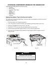
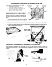
Removing the Log Valve Assembly
1. Disconnect power from the washing machine.
2. Disconnect the water supply hoses from the inlet valves.
3. Remove the 1/4” screw securing the log valve at the rear of the washer top.
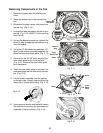
4. Place the console in the service position.
5. Disconnect the wiring harness connectors from the terminals of the six (6) valve solenoids and
the thermistor terminals.
6. Depress the tabs on the inner splash shield and push the tabs through the washer top.
7. Push the rivet tab through the washer top to release the rivet securing the splash shield.
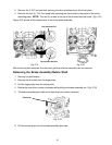
8. Reattach the console to the washer top.
9. Raise the washer top to the service position. See procedure on next page.
10. Remove the inner splash shield.
11. Remove the rivet securing the log valve to the washer top.
12. Disconnect dispenser hoses.
13. Remove log valve from washer
top.
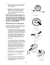
Thermistor Connector
Fig. 3-7
Relay Connectors
OPR