


14
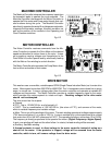
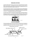
INTERLOCK SWITCHES
There are two (2) Interlock Switches located behind the front panel and the bottom panel that ground
the drive motor circuit when either panel is removed. When the machine is running with both panels
in place, the drive motor is electrically isolated from ground.
The interlock switches are normally closed and held open when the panels are in place. Removing
either panel grounds the drive motor for safety, but still allows it to operate. This condition may allow
enough current leakage to ground to trip a Ground Fault Interrupter outlet. It is not recommended to
operate the washer with either panel removed. The drive motor can only be tested for continuity in the
field. The drive motor must be disconnected from the electrical source before testing.
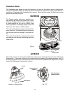
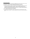
Shield Capacitor
A capacitor is in series with the interlock switches and the lower
harness shield to reduce electrical interference created by the drive
motor’s operation. The capacitor is a component of the lower
wiring harness. If the capacitor has failed, the complete lower wiring
harness must be replaced.
Shield
Capacitor
Fig. 2-10
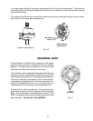
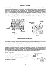
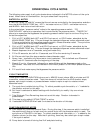
DRIVE SYSTEM
The Drive Motor operates the nutate and spin functions by reversing direction. The Drive Motor is
linked to the drive mechanisms by a stretch belt. The belt transfers the motion of the Drive Motor to a
Drive Pulley. The Drive Pulley has a splined hub, into which the Nutate Shaft is inserted and is in
motion in whichever direction the Drive Pulley is turning. The Drive Pulley, Drive Motor and Drive Belt
all turn in a clock-wise direction, as viewed from underneath when the system is Nutating. The Drive
Motor reverses direction for Spin and causes the Drive Pulley to turn in a counterclockwise direction,
as viewed from underneath. When turning in this direction, an actuating bump in the hub of the Drive
Pulley will contact the Brake Release pawl on the Spin Tube/Brake assembly. This releases the
brakes and allows the basket to spin.
Drive Pulley
Drive Motor
Drive Belt
Spin Tube/Brake
Assembly
Brake Release
Pawl
Fig. 2-8
Fig. 2-9