53
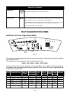
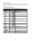
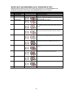
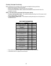
TOUCHPAD
+ LEAD - LEAD
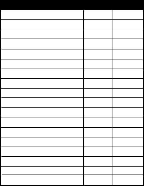
KEY SWITCH MATRIX
• If any switches fail this test, replace the console panel/touchpad assembly.
• If all switches are OK, replace the control board.
WHITEST WHITES
HEAVY DUTY
NORMAL
JEANS/DARKS
BULKY ITEMS
QUICK WASH
DELICATE/CASUAL
WOOL
HAND WASH
RINSE & SPIN
SOIL LEVEL
WATER TEMP
SOAK
EXTRA RINSE
EXTEND SPIN
CYCLE SIGNAL
STOP/CANCEL
START
P11-2
P11-3
P11-1
P11-2
P11-3
P11-1
P11-1
P11-2
P11-3
P11-1
P11-2
P11-3
P11-1
P11-2
P11-3
P11-3
P11-2
P11-1
P11-4
P11-4
P11-5
P11-5
P11-5
P11-4
P11-6
P11-6
P11-6
P11-7
P11-7
P11-7
P11-8
P11-8
P12-5
P11-8
P12-5
P12-5
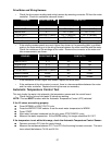
Checking Touchpad Functioning:
Before replacing the control board, check for proper touchpad functioning as follows:
• Disconnect the power cord from the outlet.
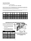
• Remove the connectors P11 and P12 from the control board.
• Using the Key Switch Matrix below, measure the resistance across the switch when the
touchpad is pressed.
NOTE: The meter must be connected with the proper polarity.
• If using an analog readout meter: The resistance reading should go from infinity (open circuit)
down to approximately 10 or 20 ohms.
• If using a digital readout meter: The resistance reading should go from infinity down to a
readable ohm level.


