


Operation Manual Section 5: Installing a transducer assembly
3-9000-744 Rev F September 2013
Installing a transducer assembly while the meter is under line pressure 31
8. Refer to Drawing CE-21060 DETAIL “A” (Appendix C).
a. Use a leak detecting fluid around the joint of the transducer holder (K) to
transducer mount (E) joint to check the seals of the transducer holder (K).
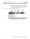
b. Clean, inspect and replace as needed the O-ring seal in the chordset coupling nut
(C). Apply a small amount of valve lubricant or other suitable grease to this
O-ring seal.
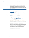
c. Grasp the chordset assembly (A). Align the slot in the chordset socket (B) with
the key pin within the transducer holder (K). Connect the chordset socket (B) to
the pins within the transducer holder (K) by pressing the chordset assembly (A)
into the transducer holder (K). After the connection has been made, turn the
chordset coupling nut (C) of the chordset assembly (A) to screw the chordset
coupling nut (C) into the transducer holder (K).
d. Verify the electrical connections by connecting to the meter using Daniel
MeterLink and select the Meter|Monitor (Detailed) view. Check the flow profile,
chord performance, gains, and Signal-to-noise ratios to ensure the transducer
signal quality is good. If transducer assembly parts were replaced with new parts,
review the notes at the beginning of this procedure for instructions on
replacement of transducer assembly parts.
e. Additional transducer assembly extractions require the disassembly of the
extractor tool and require following the disassembly procedure in Section 4.1.
LEAKAGE HAZARD
If a leak is detected, repeat the steps to remove a transducer assembly while the meter is
under line pressure (see Section 4.1).
Failure to repair the leaking transducer holder (K) seals could cause exposure to escaping gases
or an explosion resulting in possible personal injury.