


Operation Manual Section 5: Installing a transducer assembly
3-9000-744 Rev F September 2013
Installing a transducer assembly while the meter is under line pressure 25
51
Section 5: Installing a transducer assembly
5.1 Installing a transducer assembly while the meter
is under line pressure
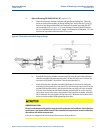
1. Refer to Drawing CE-21065 DETAIL “F” (Appendix C).
a. Review the notes in Section 2.2 at the beginning of this procedure for
instructions on replacement of transducer assemblies (J) and other mounting
parts.
b. Clean the transducer assembly (J), transducer stalk assembly (D), if fitted, and the
transducer holder (K). Take particular care to clean the transducer holder (K)
threads. Replace the O-ring seals on the transducer holder (K).
c. Clean, inspect and replace as needed, the O-ring seal on the male connector end
of the transducer assembly (J).
d. Apply a small amount of valve lubricant or other suitable grease to the O-ring seal
on the male connector end of the transducer assembly (J).
e. Align the slot on the male connector end of the transducer assembly (J) with the
pin within the mating connector female end of the transducer stalk assembly (D),
or the transducer holder (K). Press the two parts together. Equally tighten the
three set screws (W) on the transducer stalk assembly (D), or the transducer
holder (K) securing the transducer assembly (J) in place.
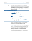
f. With the extension (L) protruding from the flange end of the lubricator chamber
assembly (M) install the transducer holder (K) by engaging the T on the extension
(L) with the T-slot on the transducer holder (K). Once the connection has been
made, retract the extractor rod (N) enough so the T-slot joint is inside the bore of
the lubricator chamber assembly (M). This secures the attachment.
g. Apply an ample amount of anti-seize compound to the threads of the transducer
holder (K). Apply a small amount of valve lubricant or other suitable grease to the
O-rings of the transducer holder (K).
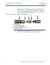
2. Refer to Drawing CE-21064 DETAIL “E” (Appendix C).
a. Fully retract the extractor rod (N) within the lubricator chamber assembly (M).
Confirmation of full retraction is indicated by a mark on the extractor rod (N) at
the end of the lubricator chamber assembly (M). When this mark is visible the
extractor rod (N) is fully retracted.
b. Clean the lubricator chamber assembly (M) end flange sealing face. Clean the
extractor tool valve assembly (H) flange sealing face. Apply a small amount of
valve lubricant or other suitable grease to the O-ring seal on the flange end of the
lubricator chamber assembly (M).
c. Rotate and align the lubricator chamber assembly (M) flange to the extractor tool
valve assembly (H) flange and attach with four cap screws (Z). Securely tighten all
cap screws (Z) evenly, keeping the faces of both flanges parallel. Minimize the
rotation of the extractor tool assembly during screw tightening.