


30 Installing a transducer assembly while the meter is under line pressure
Section 5: Installing a transducer assembly Operation Manual
September 2013 3-9000-744 Rev F
4. Refer to Drawing D-08248 (Appendix C).
a. Remove the meter housing quick connect stem and the reducer if it was
required. Return the parts to the tool kit.
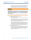
b. Disconnect the high pressure hose quick connect body (AA) from the ultrasonic
meter housing line pressure valve (Q) quick connect stem (FF) and the other high
pressure hose quick connect body (AA) from the quick connect stem (CC) on the
pressure regulator (V) high pressure (primary) port. Remove and store the high
pressure hose.
c. Disconnect the low pressure hose quick connect body (BB) from the quick
connect stem (DD) on the pressure regulator (V) low pressure (secondary) port.
Wrap the low pressure hose around the extractor tool piston assembly (P) and
connect the low pressure hose quick connect body (BB) to the quick connect
stem (EE) located on the extractor tool piston assembly (P) flange for storage.
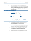
5. Refer to Drawing CE-21065 DETAIL “F” (Appendix C).
a. Loosen and remove the four extractor tool piston assembly (P) nuts (X). Minimize
the rotation of the extractor tool assembly during nut removal. Pull the extractor
tool piston assembly (P) away from the lubricator chamber assembly (M). For safe
keeping reinstall the nuts (X) after removal. Remove and store the extractor tool
piston assembly (P).
b. Loosen and remove all four of the lubricator chamber cap screws (Z) on the
lubricator chamber assembly (M) flange from the extractor tool valve assembly
(H) flange. Minimize the rotation of the extractor tool assembly during screw
removal. Pull on the lubricator chamber assembly (M) to disconnect the
lubricator chamber assembly (M) flange from the extractor tool valve assembly
(H) flange. During disassembly disconnect the extractor rod (N) end T from the
end of the extension (L) T-slot by extending the extractor rod (N) from the end of
the lubricator chamber assembly (M). Remove and store the lubricator chamber
assembly (M).
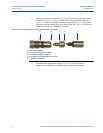
6. Refer to Drawing CE-21062 DETAIL “C” (Appendix C).
Loosen and remove the four split clamp screws (G). Remove both halves of the split
clamp (F) and store. When the split clamp (F) is fully disconnected from the
transducer mount (E) pull the extractor tool valve assembly (H) away from the
transducer mount (E). When free of the transducer mount (E) continue to pull the
extractor tool valve assembly (H) while guiding the extension (L) through the bore
of the valve. Remove and store the extractor tool valve assembly (H).
7. Refer to Drawing CE-21061 DETAIL “B” (Appendix C).
Slide the extension (L) end T from the T-slot within the transducer holder (K).
Remove and store the extension (L).