


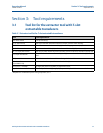


16 Steps to remove a transducer assembly from a meter while the meter is under line pressure
Section 4: Removing a transducer assembly Operation Manual
September 2013 3-9000-744 Rev F
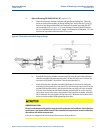
3. Refer to Drawing CE-21062 DETAIL “C” (Appendix C).
a. Verify that the seal and backup seal are present on the split clamp end of the
extractor tool valve assembly (H). Apply a small amount of valve lubricant
Molykote 111 or equivalent lubricant to the O-ring seal.
b. Using the valve handle, fully open the extractor tool valve assembly (H). The valve
is in the full open position when the valve handle contacts the valve handle stop
peg set screw (HH).
Important:
If the extractor tool valve assembly (H) is in the closed position, the valve close stop button (S)
must be depressed while the valve handle is moved to the open position.
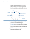
c. Slide the extractor tool valve assembly (H) over the extension (L) which has been
positioned as described in Step 2 above.
d. Position the split clamp end of the extractor tool valve assembly (H) over the
transducer holder (K) and push the split clamp end of the extractor tool valve
assembly (H) over the end of the transducer mount (E) securing the O-ring seal of
the extractor tool valve assembly (H).
Important:
If the extractor tool valve assembly (H) does not easily pass over the extension (L) the valve may
not be in the full open position. Use the valve handle stop peg set screw (HH) to adjust the valve
to the full open position. It is important that the extension (L) freely passes through the
extractor tool valve assembly (H) when the valve handle is in contact with the valve handle stop
peg set screw (HH).
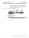
e. Install each half of the split clamp (F) over the split clamp end of the extractor tool
valve assembly (H). The flanged end of the split clamp (F) is to be closest to the
mount (E). Engage the ridges in the I.D. of the split clamp (F) into the slots in the
mount (E) and extractor tool valve assembly (H).
f. Rotate the extractor tool valve assembly (H) to position the valve stem in a
horizontal plane.
g. Secure the halves of the split clamp (F) with four screws (G). Tighten to 20
foot-pounds of torque in a star pattern between the two halves of the split clamp.
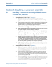
FAULTY EXTRACTOR TOOL INSTALLATION
Install the extractor tool split clamp securely to the transducer mount and make sure it is
properly seated and not loose.
Improperly seated or loose split clamp may cause the unit to fall and result in injury to personnel
or cause damage to the equipment.