


28 Installing a transducer assembly while the meter is under line pressure
Section 5: Installing a transducer assembly Operation Manual
September 2013 3-9000-744 Rev F
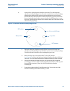
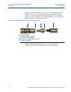
e. Adjust the pressure on the extractor tool piston assembly (P) to slightly exceed
the force of line pressure acting on the extractor rod (N).
Slowly rotate the pressure regulator (V) adjustment screw in a clockwise
direction until the extractor tool piston assembly (P) pressure, as shown on the
piston pressure gauge (U), indicates line pressure greater than the piston
pressure as shown in Table A-1.
For the line pressure indicated on the lubricator chamber pressure gauge (T),
refer to the Extractor Tool Piston Pressure chart or Table A-1. Once the pressure
given in the chart is achieved, slowly turn the adjustment screw in the clockwise
direction a little farther to allow the force of the pressure to overcome the
friction of the extractor rod (N) seals.
When the piston pressure force exceeds all of the forces acting on the extractor
rod (N), the extra ctor rod (N) will begin to slowly move towards the ultrasonic
meter. Continue until the transducer holder (K) contacts the transducer mount
(E) flange.
f. The hex nut on the extractor rod (N) should be accessible in the open space
between the lubricator chamber assembly (M) and the extractor tool piston
assembly (P). If this does not occur, retract the rod by loosening the pressure
regulator (V) adjustment screw to retract the rod (N).
g. Ensure that the valve (H) is fully open, then repeat this step. When the transducer
holder (K) contacts the transducer mount (F) the threads of the two parts should
automatically align with each other and the rod (N) hex will be accessible in the
open space between the lubricator chamber (M) and piston assembly (P). Use a
1-¼” open end wrench on the hex of the extractor rod (N) to screw the
transducer holder (K) into the transducer mount (E).
As the extractor rod (N) is rotated in the clockwise direction watch for lateral
movement of the extractor rod (N). The lateral movement will confirm thread
engagement. When tight, the transducer holder (K) is completely threaded onto
the transducer mount (E).
Important
The threaded joint of the T-slot transducer holder (K) to the transducer mount (E) does not have
a recommended torque requirement. The transducer holder (K) is to be tightened sufficiently so
the shoulder on the transducer holder (K) is fully seated.