


Operation Manual Section 4: Removing a transducer assembly
3-9000-744 Rev F September 2013
Steps to remove a transducer assembly from a meter while the meter is under line pressure 17
4. Refer to Drawing CE-21063 DETAIL “D” (Appendix C).
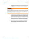
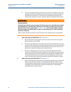
a. Clean the lubricator chamber assembly (M) end flange sealing face. Clean the
extractor tool valve assembly (H) flange sealing face. Verify that the O-ring (JJ)
located at the flange end between the lubricator chamber assembly (M) and
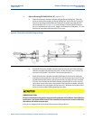
valve assembly (H) (see Figure 4-2) is not damaged. Contact Daniel Customer
Service if replacement is necessary. Apply a small amount of Molykote 111 valve
lubricant or equivalent lubricant to the O-ring seal.
Figure 4-2 Extractor tool with O-ring on flange
b. Extend the lubricator chamber extractor rod (N) from the end of the lubricator
chamber assembly (M) exposing the male T on the end of the rod. Connect the
extractor rod (N) male T to the end T-slot of the extension (L).
c. Attach the lubricator chamber assembly (M) flange to the extractor tool valve
assembly (H) flange with four cap screws (Z). Use the longer cap screw (Z) in the
top bolt hole location which is not in line with the extractor tool valve assembly
(H) valve stem. Rotate the lubricator chamber assembly (M) in such a way that
convenient access to the valves and gauges of the lubricator chamber assembly
(M) is obtained. Securely tighten all cap screws (Z). Minimize the rotation of the
extractor tool assembly while tightening the screws.
VIBRATION HAZARD
Excessive vibration on the pipeline may cause the extractor tool to vibrate. Such vibration
could cause a gas leak or other hazard. If the installed unit experiences excessive vibration,
discontinue use of the extractor tool.
If this occurs, depressurize the meter and then remove the transducers.