


26 Installing a transducer assembly while the meter is under line pressure
Section 5: Installing a transducer assembly Operation Manual
September 2013 3-9000-744 Rev F
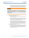
d. Align the extractor rod (N) into the center hole of the piston of the extractor tool
piston assembly (P). The piston should be fully retracted inside the extractor tool
piston assembly (P).
Important:
If the piston is not fully retracted, use a long rod or dowel to force the piston back into the
extractor tool piston assembly (P). During this process the air within the piston cylinder must be
vented through the piston orifice fitting (Y) so movement will be slow.
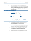
e. Attach the extractor tool piston assembly (P) to the lubricator chamber assembly
(M) by aligning the extractor tool piston assembly (P) end bolts with the
lubricator chamber assembly (M) flange bolt holes. Install and equally tighten the
four nuts (X). Minimize the rotation of the extractor assembly during nut
tightening.
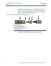
f. Connect the quick connect body (BB) on the end of the low pressure hose
attached to the extractor tool piston assembly (P) to the quick connect stem
(DD) on the low pressure (secondary) port of the pressure regulator (V).
g. Ensure that the pressure regulator (V) adjustment screw is fully loosened (coun-
terclockwise).
h. Close the lubricator chamber vent valve (R). The ultrasonic meter housing line
pressure valve (Q) and extractor tool valve assembly (H) are to remain closed.
i. Connect the quick connect body (AA) on one end of the high pressure hose to
the quick connect stem (CC) on the high pressure (primary) port of the pressure
regulator (V).