


Operation Manual List of Figures
3-9000-744 Rev F September 2013
List of Figures v
List of Figures
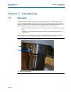
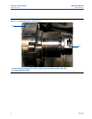
Figure 1-1 J-mount transducer identification................................................................................. 1
Figure 1-2 J-mount transducer identification ................................................................................ 2
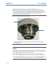
Figure 1-3 M-mount transducer identification .............................................................................. 3
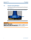
Figure 1-4 ANSI Class pressure rating stamp on lubricator chamber assembly flange ................... 4
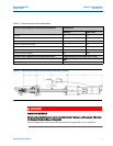
Figure 1-5 Split clamp extractor tool assembly dimensions (inches) .............................................. 5
Figure 4-2 Extractor tool with O-ring on flange............................................................................ 17
Figure 4-3 Lubricator chamber assembly flange screws .............................................................. 23
Figure 4-4 Transducer holder, stalk and transducer assembly...................................................... 24