


Operation Manual Section 4: Removing a transducer assembly
3-9000-744 Rev F September 2013
Steps to remove a transducer assembly from a meter while the meter is under line pressure 23
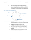
b. Loosen all four of the lubricator chamber cap screws (Z) on the lubricator
chamber assembly (M) flange from the extractor tool valve assembly (H) flange.
Minimize the rotation of the extractor tool assembly during screw removal.
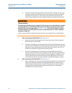
Remove the three short lubricator chamber cap screws (Z), but do not remove
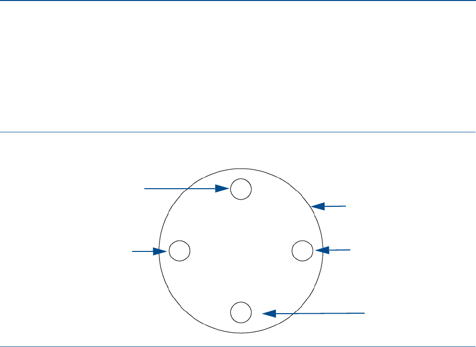
the one long lubricator chamber cap screw located at the 90
o
position. Loosen
this screw so the end of the screw is flush with the back side of the extractor tool
valve assembly (H) flange.
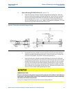
Figure 4-3 Lubricator chamber assembly flange screws
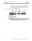
c. Pull on the lubricator chamber assembly (M) to disconnect the lubricator
chamber assembly (M) flange from the extractor tool valve assembly (H) flange.
Pivot the lubricator chamber on the remaining long cap screw.
d. Reinstall a short cap screw at either the 0
o
or the 180
o
position
(see Figure 4-3) and rest the lubricator chamber flange on the reinstalled short
cap screw. This is to leave the lubricator chamber assembly (M) bore exposed.
e. Push on the lubricator chamber extractor rod (N) exposing the transducer
assembly (J), transducer stalk assembly (D) [if fitted], transducer holder (K), and
the end of the extension (L) from the end of the lubricator chamber
assembly (M).
f. Grasp the transducer holder (K) and disconnect the T-slot in the end of the
transducer holder (K) from the extension (L) T end.
90
o
position
270
o
position
Valve assembly flange
0
o
position180
o
position