


12 Part replacement notes
Section 2: Operation preparation and part replacement notes Operation Manual
September 2013 3-9000-744 Rev F
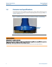
2.2 Part replacement notes
1. The following instructions are for removal and installation of one transducer assembly
(J). Repeat the following steps for each transducer assembly removal or installation
2. For accurate operation, do not exchange any transducer assembly part or parts from
the meter chord path designated by the Daniel manufacturing facility. See notes 4, 5
and 6 below for further instruction.
3. Transducer assemblies (J) in good working condition can be removed, cleaned and
reinstalled.
4. When a transducer assembly (J) is replaced, it is necessary for accurate operation to
modify the calibration parameters for the chord in which the transducer assembly
exchange occurred. This means modifying the ultrasonic meter electronics Modbus
registers for "L", Average Delay Time and Delta Delay Time for the affected chord.
5. Transducer assemblies (J) are always replaced in pairs on any given chord path. The
Average Delay Time and Delta Delay Time are included on a Calibration Sheet provided
with each transducer assembly (J) pair. The length of each transducer assembly (J) is also
provided on the Calibration Sheet, as well as, etched on the transducer assembly
external surface. See Note 7and Note 8 below for further instructions.
6. When a transducer stalk assembly (D) and/or transducer holder (K) is replaced, it is
necessary for accurate operation to modify the calibration parameters for the chord in
which the transducer parts exchange occurred. This means modifying the ultrasonic
meter electronics Modbus
1
registers for "L" for the affected chord. The length of each
transducer stalk assembly (D) and transducer holder (K) is etched on the part’s exterior
surface. See Note 7 and Note 8 below for further instructions.
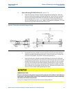
7. The value "L" is determined by adding the length of the meter housing chord to the
lengths of the transducer mounts (E) and subtracting the lengths of the transducer
assemblies (J), transducer stalk assemblies (D) [if fitted] and transducer holders (K). The
length of the meter housing chord paths and transducer mounts (E) are given on the
original calibration sheet provided with the ultrasonic meter. The length of each
transducer mount (E) is marked on the rim of the part.
8. Transducer stalk assemblies (D) are available in two inch increments of length. The style
of each part is identified by the markings on the exterior surface. Example: STYLE - S2,
STYLE - S4, STYLE - S6...etc. Transducer holders (K) are available in two lengths H1 and
H2. The H2 stalk is one inch longer than the H1 stalk. By design each ultrasonic meter
chord path has been fitted with the appropriate style of transducer stalk assembly (D)
and transducer holder (K) best suited for that transducer location. Some transducer
locations do not require a transducer stalk assembly (D). In these cases the transducer
assembly (J) is connected directly to the transducer holder (K). When replacing a
transducer stalk assembly (D) and/or transducer holder (K) it is important for accurate
operation that the exact replacement style be used.
9. The electrical circuits connecting the ultrasonic meter transducers (J) to the ultrasonic
meter electronics are intrinsically safe circuits. This feature allows these circuits to be
safely disconnected and connected in a hazardous atmosphere without the need to
disconnect power to the ultrasonic meter electronics. If the meter has more than one
pair of transducers, meter operation will only be slightly impaired by the disruption of
one pair of transducers at a time. Flow and flow measurement can continue during
extractor tool operation.