


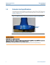

6 Extractor tool pre-use and post-use inspection
Section 1: Introduction Operation Manual
September 2013 3-9000-744 Rev F
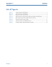
1.3 Extractor tool pre-use and post-use inspection
Prior to and after using the extractor tool, the following inspection procedure must be followed:
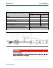
Refer to drawing D-08248 Detail D (see Appendix C).
1. Prior to connecting the Lubricator Chamber Assembly to the Piston Assembly verify
the extractor rod (N) on the Lubricator Chamber Assembly is correctly indicating by
performing the following steps.
a. Make sure the extractor rod is clean and free of dirt and it smoothly pulls in and
out of the Lubricator Chamber Assembly.
b. Grasp the extractor rod (N) and gently pull it out until it stops.
c. The scribe mark at the end of extractor rod (N) is clearly visible.
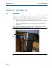
2. Visually verify that all hoses are intact with no kinks or tears.
3. Visually inspect the four bolts that hold the Piston Assembly onto the Lubricator
Chamber Assembly. Make sure they are clean and that the threads are not galled,
stripped or damaged.
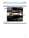
4. Make sure that there are at least eight (8) backup O-Rings
and enough lubricant to
replace all transducer holders extracted. If not enough, order enough for current and
f
uture use. See Daniel Service Group for O-Ring part numbers.
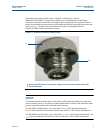
5. Perform a bench test to verify the pressure gauge and regulator on the Lubricator
Chamber Assembly are working properly. Follow Section 4.1, Step 1C to Step 6A in this
manual to prepare the Extractor tool for the bench test.
a. Close the Extractor Tool Valve (H) and use 300 psi nitrogen pressure to pressurize
the extractor tool.
b. Visually verify that there are no leaks at the NPT thread connections. Use Snoop
®
or soapy water solution for this visual leak check.
c. Confirm that the Lubricator Chamber Assembly line pressure gauge (T) is
indicating the correct line pressure. Adjust the regulator (V) to the required
piston pressure (
see pressure references Table A-1 Appendix A). Verify that the
Piston Assembly gauge (U) indicates according to Table A-1.
d. Check all Joints including ball seal for leaks using Snoop or a soapy water solution.
Turn the line pressure valve off. Use the Lubricator Chamber vent valve (R), and
bleed the line pressure from the tool. Confirm that both gauges show a slow
decrease in pressure until zero pressure is reached.
e. Close the vent valve (R).