


2 K400 Issue No. 1
reference) and a possible electrical feedback from a device under test (i. e.
temperature probes, temperature transmitters). An error calculation, with scaling
function, allows the user to check immediately the accuracy specification of the unit
under test. A 24 V auxiliary excitation provides power for temperature transmitters
under test.
1.1 Automatic Calibration
An RS232 computer interface enables a Calibration Management Software to
provide automatic calibration procedures, typically with the following capabilities:
• Creation of instrument details
• Creation of test procedures and work orders
• Analysis of devices due for calibration
• Printing of calibration reports
• Export functions
Refer to section 4 SERIAL COMMUNICATION for remote control of this instrument.
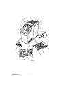
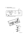
1.2 Parts Identification
Key to Figure 1-1
Fig no. Description
1
Dry well with insert
2
Protection grid
3
Carrying handle
4
4 mm socket for T/C, RTD and ohm connection, with CJ compensation
5
Tactile key-pad for direct selection of all the operating function (ramps, steps, preset
values, switch test, help, set-up) and to set temperature values
6
Cooling fan
7
Support feet (4)
8
Protection fuse (115 Vac 2x12.5 AT and 230 Vac 2x6.3 AT for DBC 650
(115 Vac 2x1.6 AT and 230 Vac 2x3.15 AT for DBC 150)
9
Main power selector 100 - 120 Vac and 220 - 240 Vac, 50/60 Hz
10
Power supply on/off switch
11
Main power socket: to connect the standard power cable
12
RS232 serial communications interface
13
Cursor (arrow) keys to select operating functions from the main menu and to move the
selection cursor through the menus
14
Digital display with Multi-language user interface
15
Switch test connection, suitable to connect test leads supplied as standard
16
4 mm socket for voltage and current input with 24V dc auxiliary excitation
17
Lemo connection for external reference probe: suitable for connecting PT 100 probes
with 3 or 4 wires, supplied with standard mating connector ( B1, B2 and B3 options)