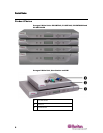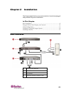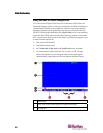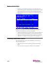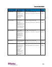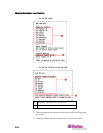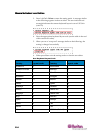
Chapter 2: Installation
39
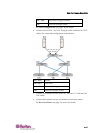
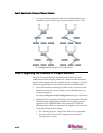
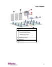
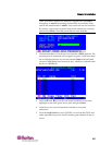
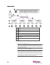
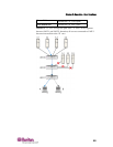
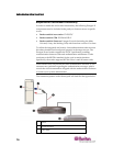
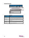
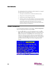
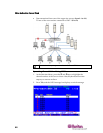
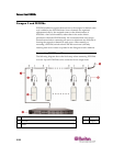
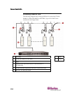
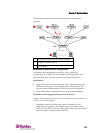
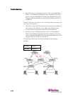
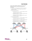
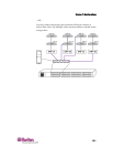
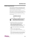
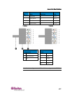
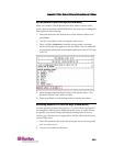
a. ConnectaCIMtoaserver—seeSpecifications(onpage172)for
specificinstructionsonconnectingdifferentCIMtypestoa
server.
b. ConnectoneendofaCat5UTPcabletotheRJ45portonaCIM.
c. ConnecttheotherendofcabletotheRJ451‐INportontheback
ofHubPac.
d. PowerONtheserver
.
e. Repeattheabovestepstoconnecttheremainingservers,
connectingtheCat5UTPcabletotheHubPacattheRJ452‐IN,
3‐IN,4‐IN,5‐IN,6‐IN,7‐IN,and8‐INportforeachconsecutive
server(2through8)added.
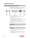
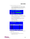
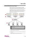
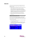
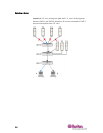
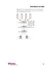
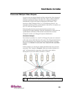
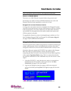
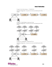
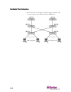
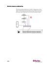
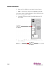
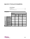
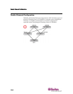
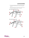
3. ConnecttheHubPactoeac
hParagonswitchbyrepeatingallofthe
followingstepsforeach5‐portclusterontheHubPac:
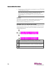
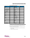
Note:Thereare8five‐portclustersontheHubPac.Foreachcluster
thenumberinfrontoftheRJ45INportrepresentstheclusternumber.
Forexample,cluster1’sfirstRJ45portis1IN,cluster2’sis2IN,and
soon.Intheinstructionsbelow,“X”representstheclusternumber(1
through8).
a. ConnectoneendofaCat5UTPcabletotheRJ45X‐1portonthe
backoftheHubPac.
b. Connecttheotherendofthecabletochannelport#Nontheback
ofoneofthedesiredParagonswitches.
c. ConnectoneendofaCa
t5UTPcabletotheRJ45X‐2portonthe
backoftheHubPac.
d. Connecttheotherendofthecabletochannelport#Nontheback
oftheseconddesiredParagonswitch.
e. ConnectoneendofaCat5UTPcabletotheRJ45X‐3portonthe
ba
ckoftheHubPac.
f. Connecttheotherendofthecabletochannelport#Nontheback
ofthethirddesiredParagonswitch.
g. ConnectoneendofaCat5UTPcabletotheRJ45X‐4portonthe
backoftheHu
bPac.
h. Connecttheotherendofthecabletochannelport#Nontheback
ofthefourthdesiredParagonswitch.
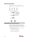
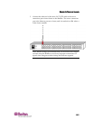
4. ConnectthepowercordtothebackoftheHubPac.PowerONthe
HubPac.
5. PowerONeachoftheParagonswitches.