135
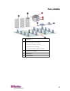
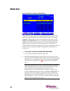
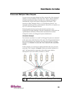
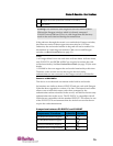
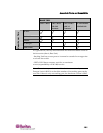
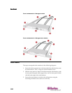
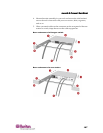
TheaimoftheMainUnits(suchasP2‐UMT1664“M”)andStackingUnits
(suchasP2‐UMT1664“S”)istoallowuserstobuildthe Paragonsystemto
includeadditionalchannelportsandthetiersuptothreelevels,sothat
moreusersandchannelscanbeconfiguredtocontrolmorese
rvers.The
systemdoesnotneedtobeover‐redundantinaccessibility,but
administratorsshouldconsidertheconfigurationsillustratedinthis
chapter.InmorecomplexstackedParagonsetups,thereareimportant
guidelinesaboutlegalandillegaldeviceconfigurationsthatmustbe
followedtoensurefunctionality.
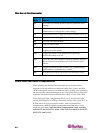
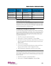
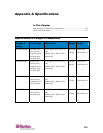
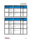
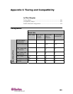
In This Chapter
PrinciplesofRe‐Connection.........................................................................135
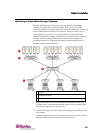
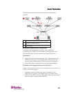
TieredCon
figurations...................................................................................136
StackedConf
igurations.................................................................................139
Non‐Stand
ardTieredConfigurations.........................................................143
Loop‐Bac
kConfiguration .............................................................................148
P2‐Hub
PacConfigurationandMultipleVideo......................................... 149
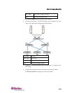
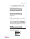
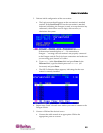
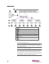
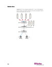
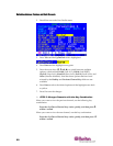
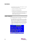
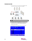
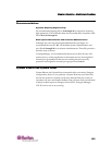
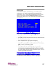
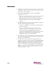
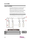
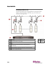
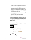
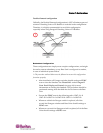
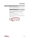
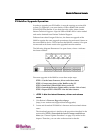
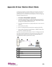
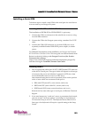
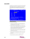
Principles of Re-Connection
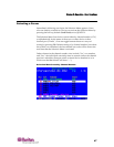
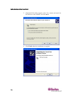
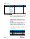
Whenachangeismadetoaconnectedtiereddevice,werecommended
thatpowertoalldevicesisrecycled,ifpossible.Thisincludesthedevice
wheretheconnectionischangeddirectly,aswellasalldevicesbelowitin
thesystemarchitecture.
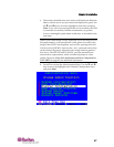
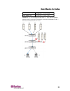
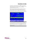
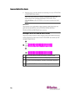
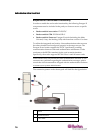
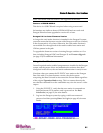
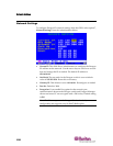
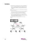
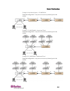
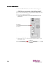
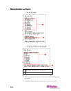
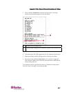
ThesequenceofpowerrecyclingshouldstartfromtheHIGHE
STtiered
deviceandendwiththeBaseUnit(first‐tierParagonswitch).For
example,ina“SingleBase”configuration(onlyoneParagonswitchasthe
BaseUnit),ifaconnectionchangeismadeatadeviceonthethirdtier,the
sequenceofpowerrecyclingshouldbeasfollows:
• Thethi
rd‐tierdevicewiththechangedconnection
• Thesecond‐tierdeviceconnectedtothethird‐tierdevice
• TheBaseUnit
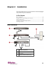
Chapter 7
Configurations