Chapter 5: Paragon II and P2ZCIMs/Z-CIMs
127
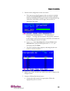
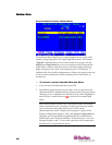
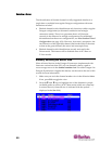
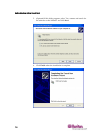
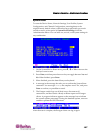
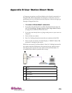
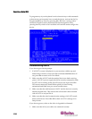
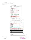
5. PowerONtheserver.
6. (Optional)ConnectalocaluserconsoletotheUKVMSCZ‐CIM.
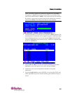
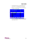
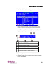
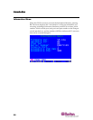
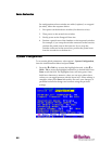
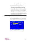
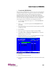
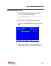
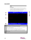
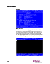
7. Namethenewlyaddedserverbyrepeatingthestepsdescribedinthe
previoussection—TonametheserverchannelontheTiered
SelectionMenuofZ‐CIM.
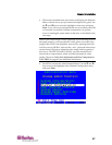
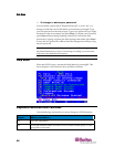
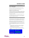
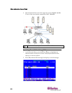
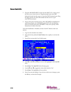
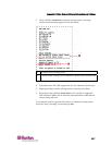
8. PressF2toreturntotheS
electionMenu.GototheZ‐CIMchannelto
verifybothofthenamechangeandtheserveroperationareOK.
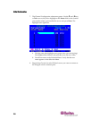
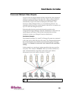
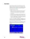
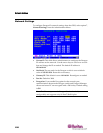
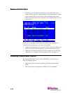
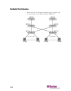
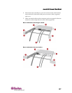
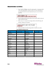
Repeatthestepsintheabovesectionsforeachservertobeaddedtothe
chain.Nameandtesteachserverasitisadded.Followthestepsbelowto
addtherestoftheZ‐CIMch
ainofservers.
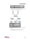
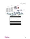
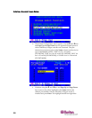
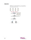
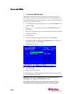
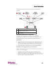
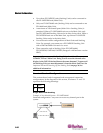
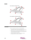
• InsertanewZ‐CIMinthechain
• NametheserverchannelonthetieredSelectionMenuofZ‐CIM
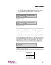
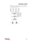
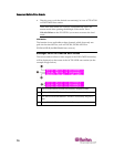
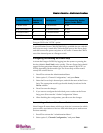
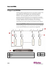
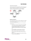
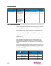
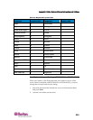
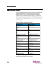
Important:Pleasefollowtheseguidelinestoensurethatthereis
enoughpowertosupportallZ‐CIMsinachain.
ForParagonIUMT242,442,832and1664withhardwareIIIand
ParagonIIfirmware,andParagonIIswitches,inchainsupto20
individualZ‐CIMunitsatleastoneZ‐CIMmustbepoweredON;in
Z‐CIMschainsfrom21to42Z‐CI
Munits,atleast15Z‐CIMsmustbe
poweredON.
Atleast75%ofUKVMSPDZ‐CIMsinthechainmustbepoweredON
inorderforthechaintoberecognizedbytheParagonswitch.
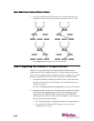
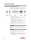
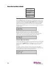
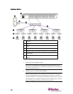
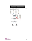
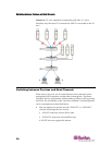
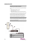
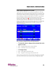
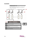
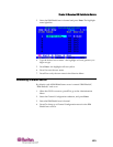
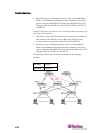
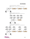
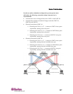
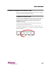
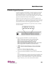
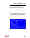
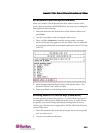
Using a UKVMSPD Z-CIM with a Local PC
TograntspecificaccesstoalocalPCfromacertainuserstationandto
accesstheParagonsystemserversalso,insertaUKVMSPDdual‐access
CIMbetweenauserstationandaBaseUnit.
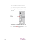
1. Ifyouhavenotalreadydoneso,installyourParagonsystemas
describedinInstallation(o
npage12).
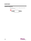
2. DisconnectthecablethatconnectstheuserstationtotheBaseUnit
fromtheBaseUnit’suserport.
3. ConnectthefreeendofthiscabletotheUKVMSPDRJ45portlabeled
“UTPOUT.”
4. ConnectanotherCat5cablefromtheUKVMSPDRJ45portlabeled
“UTPIN”toth
eBaseUnit’suserport(whereyoujustdisconnected
theothercable).