


84
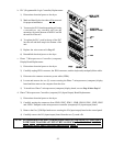
5) To install new Microprocessor Controller (computer) I/O (input/output) board, reverse Step #4 thru
Step #1.
6) Reestablish electrical power to the dryer.
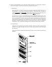
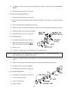
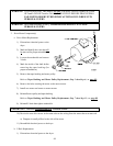
e. Keyboard (touchpad) Replacement
1) Discontinue electrical power to the dryer.
2) Disconnect keyboard (touchpad) ribbon cable from the Phase 7 microprocessor (computer) display
board.
3) Peel existing keyboard (touchpad) from the door.
4) Remove as much of the remaining adhesive (from the removed keyboard [touchpad]) as possible.
5) Install and adhere new keyboard (touchpad).
6) Reestablish electrical power to the dryer.
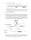
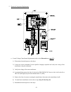
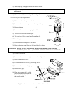
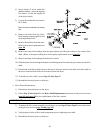
f. Switch Replacement
1) Discontinue electrical power to the dryer.
2) Mark and identify the wires that
will be
removed for proper reinstallation.
3) Remove wires.
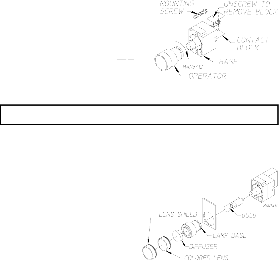
4) To remove a contact block, loosen and remove the mounting screw.
NOTE: Contact Block #1 and Contact Block #2 is normally closed (N.C.) while Contact Block #3
and Contact Block #4 is normally open (N.O.).
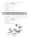
5) To remove or replace operator, loosen the two (2) screws that hold the switch body away from the
door.
6) Quarter turn the operator (in the direction shown in the above illustration) and remove.
7) Reinstall the wires removed in Step #3.
8) Reestablish electrical power to the dryer.
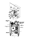
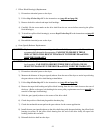
g. Switch Bulb Replacement
1) Discontinue electrical power to the dryer.
2) Unscrew clear lens shield.
3) Unscrew colored lens.
4) Remove diffuser.