


83
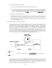
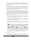
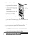
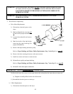
b. PLC (Programmable Logic Controller) Replacement
1) Discontinue electrical power to the dryer.
2) Mark and identify the wires that
will be removed
for proper reinstallation.
3) To remove the PLC from the mounting rail, using
a screwdriver, very carefully pull out the
mounting clip on the bottom of the PLC and lift
the unit out of the rail.
4) To replace the PLC, push in the top of the PLC
into the rail and then snap in the bottom of the
unit.
5) Replace the wires removed in Step #2.
6) Reestablish electrical power to the dryer.
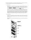
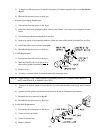
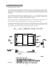
c. Phase 7 Microprocessor Controller (computer)
Display Board Replacement
1) Discontinue electrical power to the dryer.
2) Carefully unplug JPD3 connector, the JPD4 connector, and the keyboard (touchpad) ribbon cable.
3) Disconnect the common connector power cable (JPD6).
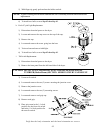
4) Loosen and remove the two (2) screws securing the Phase 7 microprocessor (computer) display
board and then remove the computer from the door.
5) To install new Phase 7 microprocessor (computer) display board, reverse Step #4 thru Step #1.
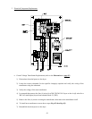
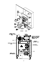
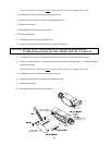
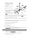
d. Phase 7 Microprocessor Controller (computer) I/O (Input/Output) Board Replacement
1) Discontinue electrical power to the dryer.
2) Carefully unplug the connectors from JPM9, JPM7, JPM11, JPM8, JPM10, JPM1, JPM2, JPM3
and, JPM4. Stamped on the microprocessor controller (computer) I/O (input/output) board.
3) Remove the five (5) Phillips head screws securing the I/O (input/output) board to the control panel.
4) Carefully remove the I/O (input/output) board from the two (2) stand offs.
NOTE: For replacement of the new I/O (input/output) board it is IMPORTANT TO HANDLE
WITH CARE TO AVOID ANY ELECTRICAL SHOCKS. DAMAGE MAY OCCUR.
PROPER STATIC PRECAUTIONS SHOULD BE TAKEN.