


66
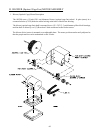
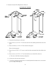
2) Auxiliary Contact Block
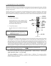
The Auxiliary Contact Block is mounted on the side of the overload. Its function is to sense an
overload trip, thereby triggering a safety fault which will disable the drying cycle. A Overload
Fault message will appear on the L.E.D. (light emitting diode) display on the Phase 7 microprocessor
controller (computer).
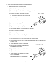
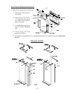
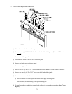
a) Auxiliary Contact Block Replacement
(1) Discontinue electrical power to the dryer.
(2) Remove the Thermal Magnetic Starter (TMS) from the din rail by pulling the tab on the
bottom of the contact block and lifting upward.
(3) Remove the two (2) wires going to the auxiliary contact block and label for correct
reinstallation.
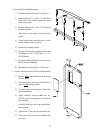
(4) There are two (2) types of auxiliary contact blocks...one with a screw and the other with a
clip...
To remove the style with the screw from the thermal magnetic starter simply remove the
screw.
To remove the style with a clip simply push in the clip and remove.
(5) To install new auxiliary contact block, reverse above procedure (Step #4 thru Step #1).
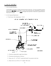
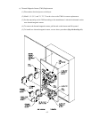
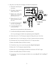
3) Varistor (MOV [Metal Oxide Varistor])
The Varistor - is used to suppress any inductive electrical spikes produced by the energizing and
collapsing of the coil voltage.
a) Varistor Replacement
(1) Discontinue electrical power to the dryer.
(2) Loosen the screws marked A1 and A2 on the contactor.
(3) Remove the varistor.
(4) Verify that no additional wires were inadvertently removed.
(5) Reverse procedure to install new varistor.