


77
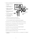
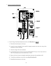
3) 24 VAC Transformer
The 24 VAC transformer consists of CB5 (Circuit Breaker) which is the primary fusing for the
transformer. For the proper rating of this circuit breaker refer to the specific electric diagram. The
transformer is located in the right hand electrical cabinet.
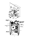
Dryer models with an optional Sprinkler System have an energizing stop relay which will disable the
dryer functions (shut the dryer down) in the event of a fire.
IF THE SPRINKLER SYSTEM IS
NOT ENERGIZED (POWERED) THE DRYER WILL NOT OPERATE. The Energizing
Stop Push Button is located on the front right electrical panel. On 2-Door models this Energizing
Stop Push Button is located on the right rear side of the electrical panel (when viewed from the
rear).
On dryer models manufactured for 208 volt or 240 volt electrical power, the voltage for the
Programmable Logic Controller (PLC) is supplied from the primary side of the 24 VAC transformer.
On dryers that are manufactured for 380 volts and higher, there is an additional secondary 240 VAC
on the transformer that is used to supply the voltage required to operate Programmable Logic
Controller (PLC) through CB6 (Circuit Breaker).
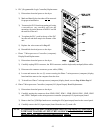
4) 24 VAC Control Circuit
The secondary side of the 24 VAC transformer supplies 24 VAC to various control circuits through
CB7 (Circuit Breaker) circuit breaker amperage (rating) is dependent on the voltage that the dryer
was manufactured with.
The first circuit is the control voltage on/off. Control voltage (24 VAC) goes through the Master
Off (normally closed) switch and supplies voltage to the Master On (normally open) switch.
When the Master On switch is momentarily engaged, the master control relay (MCR) engages.
If the power is interrupted or the Master Off switch is pressed the MCR will disengage.
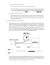
For dryers manufactured with Automatic Doors - the purpose of the supply air is to relieve pressure
on the automatic door pistons when an EMERGENCY STOP (E-Stop) is engaged.
5) Safety Circuits
The following circuit branches are to verify various safeties, if ALL conditions are met...
a) The first two (2) items are the Auxiliary Contact located on the blower (squirrel cage fan) motor
and the Tumbler (Basket) Motor Overload. If either of these devices trip, it will open up the
safety circuit thereby preventing the dryer from operating.
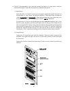
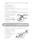
b) Front Doors Closed circuit branch.
There are two (2) magnetic proximity switches mounted in the door closed position and a magnet
mounted on top of the doors. When this magnet aligns with the proximity switch, the contacts in
the proximity switch close. When both doors are closed, the FDRC (front doors closed) L.E.D.
(light emitting diode) is on.