


79
Next reverse leads to temp sensor black to black and red to white. At that point youll measure
approximately 1.8 amps this is the turn on voltage of the device. If you hold the temp sensor in your
hands and warm it the reading will decrease corresponding to a higher current flow (the decrease is
very slight tenths of a volt).
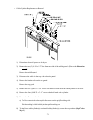
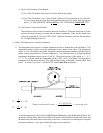
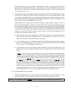
2) The Rotational Sensor is a magnetic proximity switch that is mounted on the tumbler (basket) wrapper
on the left side of the dryer. There is a magnet mounted to the side of the tumbler (basket). After
each rotation of the tumbler (basket), the magnet passes by the proximity switch causing the contacts
to close and pulse the Phase 7 microprocessor controller (computer). Whenever the magnet is over
the proximity switch there should be contact closure.
When a drying cycle is started, the blower (fan and impellor) output switches on putting 24 VAC on
the blower (fan and impellor) contactor coil, which in turn pulls in the contactor starting the blower
motor turning. Through the contactor relay this also triggers an input signal to the PLC (Programmable
Logic Controller) disabling the tilting function. Moments later, the tumbler (basket and drum) begins
to rotate because the output turns on thereby pulling in the tumbler (basket and drum) forward
contactor. Next, the Heat On/Off output will turn on if there is a call for heat, suppling 24 VAC to
the heat circuit through the safety circuits.
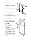
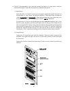
a) The first safety circuit is the Manual Reset Exhaust Hi-Limit which is located on the bracket
above the lint basket with the temperature sensor. On a temperature rise of 225º F (107º C) or
higher, the thermal switch opens breaking the heat circuit.
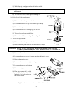
b) A second safety circuit is the Manual Reset Burner Hi-Limit Switch located on the side of the
burner. On a temperature rise of 330º F (166º C) or higher, the thermal switch opens breaking
the heat circuit, this switch must be manually reset.
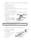
c) A third safety circuit is the Sail Switch which is attached to the front of the burner box. This
device pulls in when the impellor (fan and blower) is operating correctly and verifies proper
airflow.
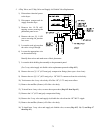
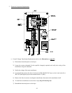
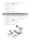
If
ALL the safeties are properly maintained, 24 VAC will enable the Direct Spark Ignition (DSI)
Module and a try for ignition begins. The DSI module induces a spark (at the spark electrode)
and then opens (energizes) the gas valve for 8-seconds attempting to light the burner. If after 8-
seconds the burner does not light off DSI module will go into a LOCKOUT Mode (the gas
valve will be de-energized and the spark will be removed from the ignitor) and will not try to light
the burner again until power is again cycled to the DSI module. If the spark produces a flame
then a microamp signal is created between the flame-probe and ground which in turn will keep
the burner on. The Heat On or Off output cycles the heat unless there is a fault at a safety
sensor. At the end of a cycle the air jet output turns on to clean off the impellor fan. The audio
alert output energizes the 24 VAC Audio Alert horn mounted on the right door, the end of cycle
output energizes the 24 VAC End of Cycle light found on the top of the front panel.
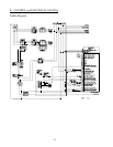
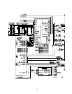
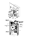
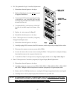
b. PLC (Programmable Logic Controller)
1) The PLC (Programmable Logic Controller) can consist of one (1) or two (2) modules; a main
module and in some cases an expansion module is used for additional inputs and outputs.
NOTE: The information listed on page 80 is generic in nature, refer to blueprints for specific details.