


80
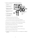
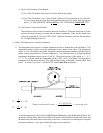
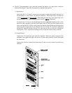
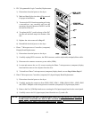
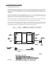
a) The PLC (Programmable Logic Controller) module has thirteen (13) input relays which are
labeled #0 through #13 and nine (9) output relays labeled #0 through #9.
(1) Input Relays
Input relays #0, #1, #2, and #3 are set up as user inputs to signal what specific function is to
be performed (i.e., load, unload, tilt, and front identifier). These input relays are charted as
1 and 0 (
1 is logic on and 0 is logic off). When either an input relay or an output relay is on,
the appropriate L.E.D. (light emitting diode) on the PLC will be illuminated.
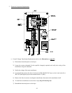
For input relay #7 to turn on, the left and right front doors must be completely open. Once
these doors are completely open, the jog forward (input #5) and jog reverse (input #6) can
turn on through the PLC which in turn rotates the tumbler (basket and drum) through either
output relay #0 or output relay #1 providing the lint door is closed. This interlock is performed
through PLC input #9 (lint door closed), or in some cases the drive or blower overload may
interrupt the 24 VAC signal from reaching the drive contactors and the tilting solenoids.
(2) Output Relays
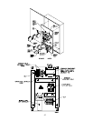
Output relay #2 controls the open front door function. When this signal is energized, the
pneumatic valve opens allowing air into the two (2) door cable cylinders, which in turn opens
the front doors.
Output relay #0 (drive forward) and output relay #1 (drive reverse) are used to perform jog
functions.