


31
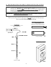
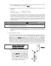
a) Connect the water column test gauge (manometer) to the gas valve pressure tap (1/8 N.P.T.).
Refer to the illustration on previous page (
page 30).
b) Start the dryer...with the burner on, the correct water column pressure (W.C.) reading in inches
should be:
Natural Gas ------------------ 3.5 inches W.C. (8.7 mb).
L.P. (liquid propane) Gas -- 10.5 inches W.C. (26.1 mb).
When a gas dryer is first started (during initial time of installation or start-up), it has a tendency
not to ignite on the first ignition attempt. This is due to the fact that the gas supply piping is filled
with air, so it may take a few minutes for the air to be purged from the supply lines. During this
purge period there may be insufficient gas pressure for ignition, which might cause the DSI
module to go into the LOCKOUT mode (the L.E.D. [light emitting diode] will BLINK GREEN
CONTINUOUSLY).
NOTE: During the purge period, check to be sure that ALL shut-off valves are open.
NOTE: To reset the DSI module if it is in the LOCKOUT mode, Burner Control Fault will display.
To clear this fault press the CLEAR/STOP key.
c) If gas pressure is low, unscrew slotted regulator cover on top of the gas valve and turn regulator
(pressure) adjustment screw (located underneath the cover) clockwise (CW) to increase the
pressure.
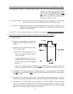
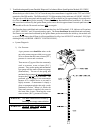
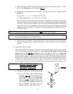
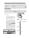
2) Ignitor/Flame-Probe Assembly
The Ignitor/Flame-Probe Assembly consists of a ceramic insulated ignitor electrode, a ground rod,
and a ceramic insulated flame-probe electrode. The GAP between the ignitor electrode and the
ground rod is set, and must be maintained at 1/8 (3.175 mm) +/- 1/32 (+/- 0.79248 mm).
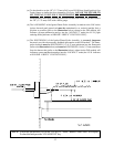
When the DSI (Direct Spark Ignition) module provides the high synchronous spark (14,000 volts)
through the high voltage (HV) lead, a spark is produced over the GAP. When this spark is produced,
the gas valve is opened. Upon ignition, the flame-probe electrode (of the Ignitor/Flame-Probe
Assembly) has high voltage provided to it that supplies a small current to ground through the flame.
Once the current is sensed, it initializes the DSI module to sustain the gas flow (from the gas valve).
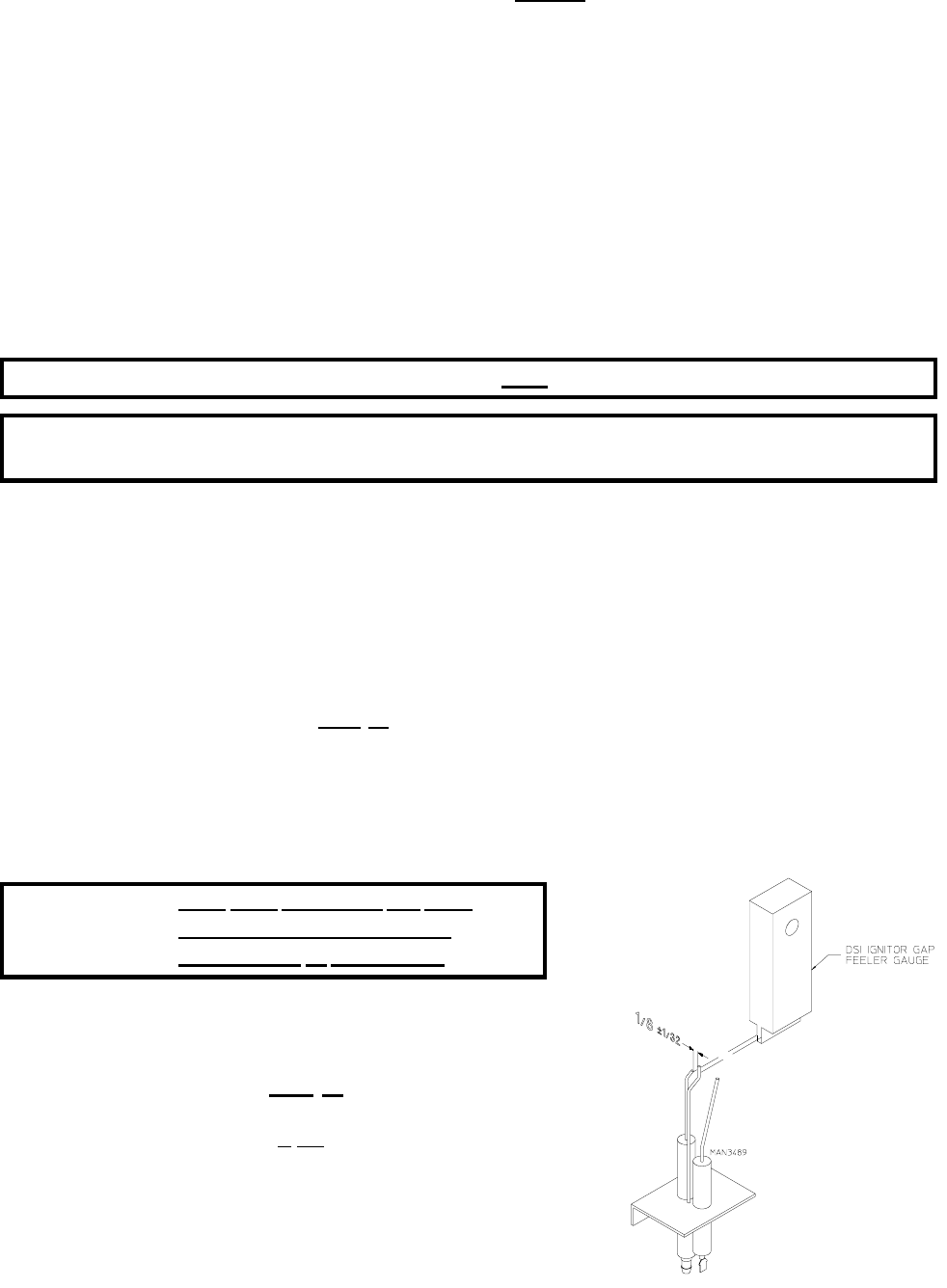
IMPORTANT: THE GAP SETTING ON THE
IGNITOR/FLAME-PROBE
ASSEMBLY IS CRITICAL.
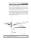
a) DSI Ignitor/Flame-Probe Assembly Adjustments
(1) The GAP on the Ignitor/Flame-Probe
Assembly must be set, and held at 1/8
(3.175 mm) +/- 1/32 (+/- 0.79248 mm).
If this GAP is not maintained (if the GAP is
either too large or too small), the DSI module
will indicate a system malfunction and go into
the LOCKOUT mode (the L.E.D. will
BLINK GREEN CONTINUOUSLY).