


95
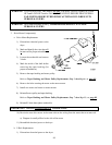
11) Replace
ALL wires removed in Step #5 (previous page [page 94]).
12) Mount the top of the thermal magnetic starter to the top of the din rail and press down and in.
Inspect ALL of the work performed.
13) Set the control of the thermal magnetic starter to the start position.
14) Reestablish electrical power to the dryer.
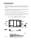
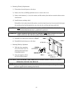
6. Rotational Sensor Assembly
The Rotational Sensor Assembly is located on the right hand side of the dryer tumbler (basket) section. It
consists of a magnetic rotational switch, mounted on the bracket which is bolted to the tumbler (basket)
section. A magnet is riveted to the tumbler (basket) of the dryer.
The magnetic rotational sensor switch senses the rotation of the tumbler (basket). If the gap between the
sensor switch and the magnet is greater than a preset amount, then the dryer will shut down on Rotational
Sensor Failure.
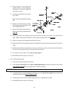
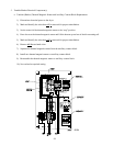
a. Rotational Sensor Switch Replacement
1) Discontinue electrical power to the dryer.
2) Remove the two (2) TEK screws securing the rotational sensor bracket to the tumbler (basket)
section.
3) Remove the magnetic rotational sensor switch from the mounting bracket, by removing the adjustment
nut.
4) Depress the tabs on the rotational sensor harness plug and pull apart, then remove the sensor switch.
5) To install a new sensor switch, connect the plug of the new sensor switch to the sensor harness.
6) Place one (1) adjustment nut onto the sensor switch and insert into the mounting bracket.
7) Place the second adjustment nut on but DO NOT tighten. The magnets on the tumbler (basket) and
the sensor switch must be in a horizontal line to one another.
8) The gap between the magnet and the sensor switch must be 1/8-inches (3.175 mm).
9) Tighten the adjustment nuts installed in Step #7 and Step #6.
10) Reestablish electrical power to the dryer.